Cement Mill Process:
The Cement Mill Process has different Stages in Cement Production and they are
The raw materials of Cement Mill Process are lime and silica. Alumina and ferric oxide are used as fluxing agents.
- Collection of raw materials such as lime stone. This is transported to the mill site and crushed there if the quarry is far off. If the quarry is nearer it is crushed at the quarry itself and transported to the mill site.
- Grinding of this crushed lime stone after the addition with bauxite, iron ore, etc. By passing air through bottom the lime powder is homogenised
- This is fed to the cement kilns where the cement clinker is made at high The process where dry powder is used is called dry process.
- Wet Cement Mill Process are also popular. Here the slurry is made by crushing or grinding the lime stone, bauxite with water. This is then fed to the kiln through the kiln feed tank.
- Dry process is preferred to wet process due to the reduced quantity of fuel required. However the latter becomes economical if the materials are already wet and drying them may not be economical.
- The hot clinker is then air cooled in special types of coolers and made ready for storage.
- After storing for a few days gypsum is added in required quantities and ground to the required fineness.
Every stage has its own drive. Several drives in Cement Mill Process are raw mill drives, cement mill drives, kiln drives, crusher drives, waste gas fan drives and compressor drives.
Requirement of Mill Motors:
- They should have high starting torque. The starting current must be limited to a maximum of two times full load value to minimise voltage dips. The breakdown torque should alsd.be high so that sufficient overload capacity is available.
- An overload capacity of 50% for one minute may be necessary, occurring for four times in an hour.
- Three starts from cold conditions and two consecutive starts from hot conditions per hour against full load.
These are very well met by a three-phase slip ring induction motor. Suitable starting torques may be accomplished at reduced starting currents by means of rotor resistance. The motor must have sufficient thermal rating to have frequent starts both under cold as well as hot conditions. The power factor may be improved by capacitor bank.
The power rating of the motor is rather high. As the motors have large power ratings and power transmission using gear boxes at this power level is not practical, two motors of identical capacity arc used. Both of them may be equipped with identical rotor starters.
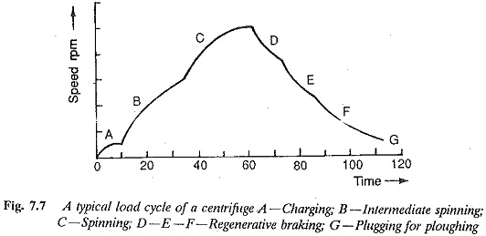
Gearless drives are preferable here. Gearless drives using the principle converters (Fig. 7.7) or dc link converters may also be used. As the price of thyristors is becoming less, these thyristorized drives are becoming very popular.
Kiln Drives:
The rotary kiln drives depend upon the type of Cement Mill Process (wet or dry). These are, in general, tubular tilted from the horizontal position with a ring fitted around them. This ring gear engages with one or two pinions. A variable speed motor drives the pinion.
The requirements of a kiln motor are the following:
- Power requirement is very high.
- Speed control ratio is 1:10. Very low creeping speeds of 1 rpm may be required.
- Starting torque should be in the range 200 to 250% of full load torque.
- The acceleration of the drive should be completed in about 15 s.
- For small periods an overload capacity of 200-250% may be required.
- The motor must have suitable control for inching and spotting during maintenance.
The motors that meet the above requirements are ac commutator motors and Ward Leonard controlled dc motors. These have the disadvantage that the highest rating is limited by the commutator. Speed range is 1:2 in ac commutator motors whereas a speed range of 1:10 with crawling speeds is possible with dc motors. Capital outlay, lower efficiencies and limitations due to commutator, either in the Ward Leonard or ac commutator motors, may be overcome by the use of thyristorized drives. These have a wide range of speed control as against ac commutator motors.
When two motors are used to deliver the power they must be designed to have equal load sharing without overloading any one of them. They must maintain the same speed. They may be series connected or parallel connected with closed loop speed control
Converter fed dc motors in static Ward Leonard control have limitations on maximum operating speed and power rating due to the presence of a mechanical commutator. The ripple content in the armature current and possible discontinuous conduction further affect the commutating capability of the motor. Therefore for power ratings beyond this value, ac drives are suitable. Tubular mills for Cement Mill Process are very slow speed high power loads. A cycloconverter fed synchronous motor meets the requirements of a drive motor. The salient features of this system are:
- The drive can be controlled to have an excellent dynamic behaviour with fast regenerative reversal.
- The converter can be used for synchronous starting by varying the frequency with smooth acceleration up to desired speed. The disadvantages, such as peak starting current and consequent voltage dips in the supply, can be completely eliminated.
- A continuous gearless drive is possible at crawling speeds.
- A motor with self control has the characteristics of a dc motor with respect to both steady-state and dynamic behaviour. It is free from hunting. It is mechanically strong, requiring little maintenance and can be built to have a rating several times that of converter fed dc motors. The low inertia of the motor is also responsible for the fast response.
- A four quadrant operation is simple and straightforward.
- Poor line power factor similar to that of converter fed dc motor.
- Field weakening is possible above base speed.
- The smooth speed control with minimal torque pulsations particularly at low speed is an added attraction, mainly when compared to synchronous motors or dc link converters.
Crusher Drives
The requirements of a crusher drive are as follows:
- The starting torque is of the order of 160% of full load torque.
- The breakdown torque is of the order of 200-250% of full load torque.
- The rotor must be capable of withstanding a locked rotor current without limiting equipment, for one minute. This kind of situation may occur in case of jamming of the crusher due to very big boulders.
- Adverse conditions of Loading may be encountered.
- Overload capacity of 15% for 15 s and 20% for 10 s may be required. Slip ring induction motor with rotor resistance starters and speed control may be suitable for crusher drives. A dc chopper can be used to control the resistance.
Fan or Blower Drives
The drive motors are located in outdoor or semioutdoor locations. Totally enclosed fan cooled motors are suitable, depending upon the location of the motor. The torque requirements are: Starting torque is 120% full load torque;breakdown torque 200-250% full load torture.
Slip ring induction motors with rotor resistance control are suitable as drive motors. A subsynchronous converter cascade in the rotor circuit may also be employed for speed control. The latter has improved efficiency of operation. The following are the features of this drive:
- The design rating of the converter depends on the speed range required. The converter must be capable of handling high currents at high speed and high voltages at low speed. Using a switchable converter cascade the rating may be decreased.
- When the lowest speed is other than zero, starting equipment is required. Under emergency conditions the motor may be required to operate with this resistance as a conventional motor. The resistance must be able to withstand the operation under running conditions.
- The torque developed has pulsations and harmonics causing heating. A 12 pulse converter may be used to reduce these effects. The line side inverter presents several harmonics to the line which may cause the distortion of the input voltage to the stator.
- It has a very poor power factor. Methods are available to improve the line p.f.
Compressor Drives
The drive motors for compressors have a rating in the range of 300-450 kW. Compressors have to be started on load or sometimes there may be means of unloading for starting. For starting on load, high starting torque is required. Normally care must be taken while choosing a starting equipment to limit the starting current. Starting current peaks are not permitted as they cause disturbances such as voltage dips. Totally enclosed fan cooled motors capable of operating in the speed range of 750-1000 rpm are employed.
Conventional squirrel cage motors may be used if starting on no-load can be accomplished. The starting method may be reduced voltage starting, to limit the starting current. If the compressor has to start on the load, high starting torque at reduced starting current may be required. A slip ring induction motor with rotor resistance starter may be used.
The ac drives making use of an induction motor or synchronous motor whose speed is controlled by means of a static frequency converter may also be used. These converters can be used for starting purposes also. They provide better starting conditions. A sufficient amount of accelerating torque with a current of 1.5 times full load current may be achieved. Locked rotor current and torque loose their significance and it is just sufficient to have reserve torque for acceleration. Consequently, voltage dips and the severe burden on the mains may be avoided. When synchronous motor are used, the line side converter uses line commutation and the machine side converter uses machine voltages for commutation. Therefore a simple converter is sufficient. Only at low speeds is the commutation assistance required.