High Voltage Engineering

High Voltage Test Bushings

High Voltage Test Bushings: High Voltage Test Bushings Consisting of Three tests, namely Power Frequency Tests Impulse Voltage Tests Thermal Tests Power Frequency Tests: Power Factor—Voltage Test: In this test, the bushing is set up as in service or immersed in oil. It is connected such that the line conductor side of the high voltage Schering […]

High Voltage Test Bushings Read More »

High Voltage Test on Insulators

High Voltage Test on Insulators: The High Voltage Test on Insulators that are normally conducted are usually subdivided as Type tests and The routine tests. Type tests are intended to prove or check the design features and the quality. The routine tests are intended to check the quality of the individual test piece. Type tests

High Voltage Test on Insulators Read More »

Classification of High Voltage Testing Methods

Classification of High Voltage Testing Methods: Classification of High Voltage Testing Methods are divided into two groups: Power Frequency Withstand Voltage Impulse withstand voltage Tests These tests together ensure the over voltage withstand capability of an apparatus. The Basics Terminology techniques of the technical terms are discussed here. In test codes and standard specifications, certain

Classification of High Voltage Testing Methods Read More »

Partial Discharge Measurements

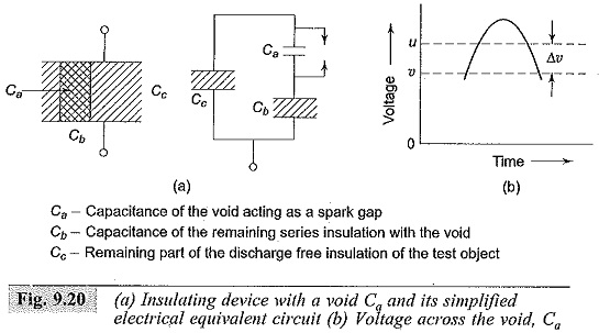
Partial Discharge Measurements: Earlier the testing of insulators and other equipment was based on the insulation resistance measurements, dissipation factor measurements and breakdown tests. It was observed that the dissipation factor (tan δ) was voltage dependent and hence became a criterion for the monitoring of the high voltage insulation. In further investigations it was found

Partial Discharge Measurements Read More »

Schering Bridge Theory

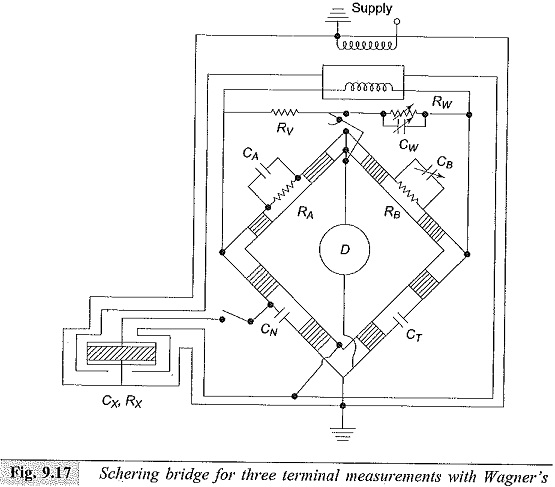
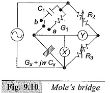
Schering Bridge Theory for Three Terminal Measurement: For two terminal measurements the bridge is grounded at its junction points. The supply transformer, detector, and all the components of the bridge are enclosed in earthed shields. For Schering Bridge Theory for Three Terminal Measurement, it is necessary to avoid stray capacitances, for accurate measurements. Hence, a

Schering Bridge Theory Read More »

High Voltage Schering Bridge

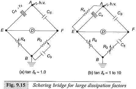
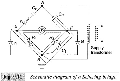
High Voltage Schering Bridge: In the power frequency range (25 to 100 Hz) High Voltage Schering Bridge is a very versatile and sensitive bridge and is readily suitable for high voltage measurements. The stress dependence of K′ or εr and tan δ can be readily obtained with this bridge. The schematic diagram of the High Voltage

High Voltage Schering Bridge Read More »

Dielectric Constant and Loss

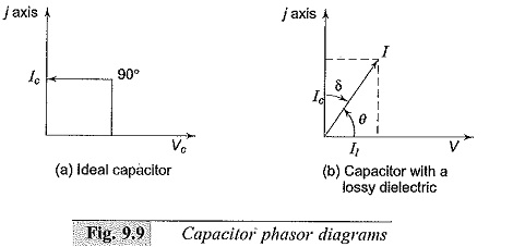
Dielectric Constant and Loss: Many insulating substances have dielectric constant greater than unity and have Dielectric Constant and Loss when subjected to a.c. voltages. These two quantities, namely, the dielectric constant and the loss depend on the magnitude of the voltage stress and on the frequency of the applied voltage. When a dielectric is used

Dielectric Constant and Loss Read More »

Direct Current Resistivity Method

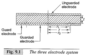
Direct Current Resistivity Method: The specimen shape and the electrode arrangement should be such that the Direct Current Resistivity Method can be easily calculated. For a solid specimen, the preferable shape is a flat plate with plane and parallel surfaces, usually circular. The specimens are normally in the form of discs of 5 to 10

Direct Current Resistivity Method Read More »

Scroll to Top