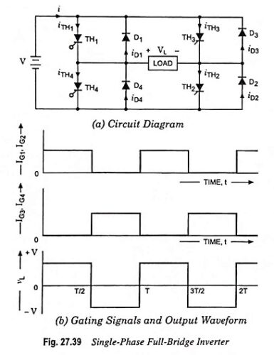
Power Converters

Inverter – Definition and Classification of Inverters

Inverter – Definition and Classification of Inverters: A device that converts dc power into ac power at desired output voltage and frequency is known as an inverter. Some industrial applications of inverters are for adjustable-speed ac drives, induction heating, standby aircraft power supplies. The dc power input to the inverter may be battery, fuel cells, …

Inverter – Definition and Classification of Inverters Read More »

Three Phase Cycloconverter – Types, Working and Applications

Three Phase Cycloconverter – Types, Working and Applications: A cycloconverter converts ac at one frequency to an ac of another frequency. Cycloconverters can be classified as single-phase to single-phase, three-phase to single-phase and three-phase to 3-phase devices. They can also be classed as step-up and step-down cycloconverters. A step-up cycloconverter provides an output whose frequency …

Three Phase Cycloconverter – Types, Working and Applications Read More »

Step up Step down Chopper or Buck Boost Converter – Working Principle

Step up Step down Chopper or Buck Boost Converter – Working Principle: A chopper can also be used for stepping up or down the supply voltage by varying its duty cycle. This is also known as a buck-boost converter. The principle of operation is illustrated in Fig. 27.29. As shown, the output voltage polarity is …

Step up Step down Chopper or Buck Boost Converter – Working Principle Read More »

Step up Chopper – Definition, Circuit Diagram and its Working Principle

Step up Chopper – Definition, Circuit Diagram and its Working Principle: In a step-down chopper the output voltage lies between zero and supply voltage. However, there are techniques by which the output of a chopper obtained is higher than the supply voltage. Such types of choppers are called Step up Chopper. The circuit diagram of …

Step up Chopper – Definition, Circuit Diagram and its Working Principle Read More »

Single Phase Dual Converter Circuit Diagram with Four Quadrant of Operation

Single Phase Dual Converter Circuit Diagram with Four Quadrant of Operation: We have seen that Single Phase full Converters with inductive loads allow only a two-quadrant operation. If two of these full converters are connected back to back, it is known as Single Phase Dual Converter as depicted in Fig. 27.20 (a) , both the …

Single Phase Dual Converter Circuit Diagram with Four Quadrant of Operation Read More »

Single Phase Full Wave Controlled Rectifier (or Converter)

Single Phase Full Wave Controlled Rectifier (or Converter): In case of Single Phase Full Wave Controlled Rectifier (or Converter) both positive and negative halves of ac supply are used and, therefore, the effective value of dc voltage is high and ripple content is less compared to half-wave rectifiers. There are two basic configurations of Single …

Single Phase Full Wave Controlled Rectifier (or Converter) Read More »

Scroll to Top