Astable Multivibrator Using IC 555:
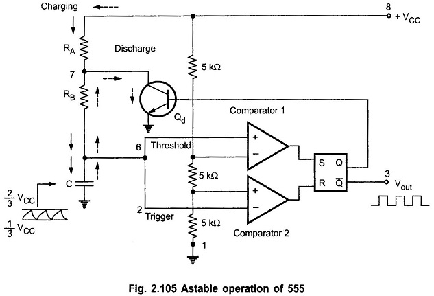
Fig. 2.105 shows the operation of Astable Multivibrator using 555 Timer IC. The threshold input is connected to the trigger input. Two external resistances RA, RB and a capacitor C is used in the circuit.
This circuit has no stable state. The circuits changes its state alternately. Hence the operation is also called free running nonsinusoidal oscillator.
Working of Astable Multivibrator using IC 555:
When the flip-flop is set, Q is high which drives the transistor Qd in saturation and the capacitor gets discharged. Now the capacitor voltage is nothing but the trigger voltage. So while discharging, when it becomes less than 1/3 VCC, comparator 2 output goes high. This resets the flip-flop hence Q goes low and Q̅ goes high.
The low Q makes the transistor off. Thus capacitor starts charging through the resistances RA, RB and VCC. The charging path is shown by thick arrows in the Fig. 2.105. As total resistance in the charging path is (RA + RB), the charging time constant is (RA + RB) C.
Now the capacitor voltage is also a threshold voltage. While charging, capacitor voltage increases i.e. the threshold voltage increases. When it exceeds 2/3 VCC, then the comparator 1 output goes high which sets the flip-flop. The flip-flop output Q becomes high and output at pin 3 i.e. Q̅ becomes low. High Q drives transistor Qd in saturation and capacitor starts discharging through resistance RB and transistor Qd. This path is shown by dotted arrows in the Fig. 2.105. Thus the discharging time constant is RB C. When capacitor voltage becomes less than 1/3 VCC, comparator 2 output goes high, resetting the flip-flop. This cycle repeats.
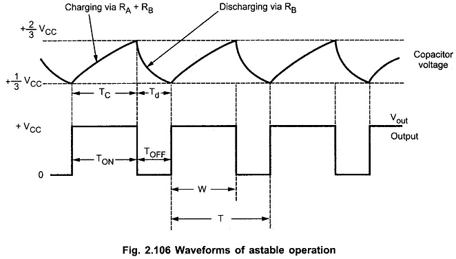
Thus when capacitor is charging, output is high while when it is discharging the output is low. The output is a rectangular wave. The capacitor voltage is exponentially rising and falling. The waveforms of Astable Multivibrator using 555 Timer IC are shown in the Fig. 2.106
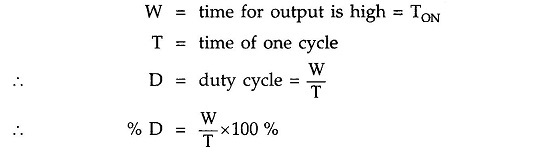
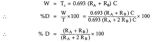
Duty Cycle of Astable Multivibrator:
Generally the charging time constant is greater than the discharging time constant. Hence at the output, the waveform is not symmetric. The high output remains for longer period than low output. The ratio of high output period and low output period is given by a mathematical parameter called duty cycle. It is defined as the ratio of ON time i.e. high output to the total time of one cycle. As shown in the Fig. 2.106.
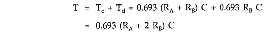
The charging time for the capacitor is given by,
![]()
While the discharge time is given by,
![]()
Hence the time for one cycle is
While
While the frequency of oscillations is given by,

If RA is much smaller than RB, duty cycle approaches to 50% and output waveform approaches to square wave.
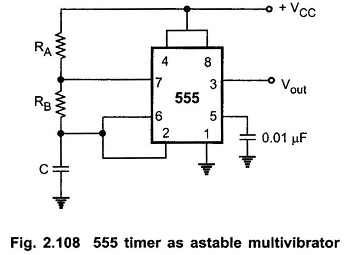
Schematic Diagram of 555 Timer Astable Multivibrator:
The Fig. 2.108 shows the Schematic Diagram of Astable Multivibrator using 555 Timer IC circuit. It shows only the external components RA, RB and C. The pin 4 is tied to pin 8 and pin 5 is grounded through a small capacitor.
The important application of astable multivibrator is voltage controlled oscillator (VCO).
Application of Astable Multivibrator using IC 555:
The various Application of Astable Multivibrator using IC 555 are,
- Square wave generation
- FSK generator
- Voltage controlled oscillator (VCO)