Voltage Level Detectors:
Voltage Level Detectors – Operational amplifiers are often used in circuits in which the output is switched between the positive and negative saturation voltages, +Vo(sat) and -+Vo(sat). The actual voltage change that occurs is known as the output voltage swing. For many op-amps, the output saturation voltages are typically the supply voltage levels minus 1 V.
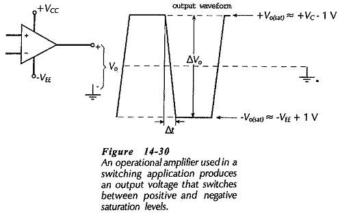
Thus, as illustrated in Fig. 14-30, the typical output voltage swing is,
![]()
For many op-amps the output can be switched from one supply level to the other (there is no 1 V drop), so that
![]()
This is referred to as rail-to-rail operation.
The switching speed, or rate-of change, of the op-amp output voltage is termed the slew rate (SR). Referring to Fig. 14-30,
Suppose the output changes from -10 to +10 V; the voltage change is ΔV = 20 V. If the transition time is Δt= 1 μs, the slew rate is 20 V/μs.
Another integrated circuit known as a voltage comparator is often substituted in place of an operational amplifier in switching applications. Voltage comparators are similar to op-amps in that they have two (inverting and noninverting) input terminals and one output. However, comparators are designed exclusively for switching, and they have slew rates much faster that those available with op-amps.
Zero Crossing Detector:
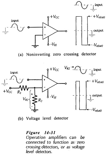
The zero crossing detector circuit in Fig. 14-31(a) is seen to be simply an operational amplifier with the inverting input grounded and the signal applied to the noninverting input. When the input is above ground level the output is saturated at its positive maximum, and when the input is below ground the output is at its negative maximum level. This is illustrated by the input and output waveforms which show that the output voltage changes from one extreme to the other each time the input voltage crosses zero. The input waveform could have any shape (sinusoidal, pulse, ramp, etc.), and the output will always be a rectangular-type wave.
The actual input voltage that causes the output to switch is not precisely zero, but some very small voltage above or below zero, depending upon the op-amp open-loop gain.
If the op-amp non-inverting input is grounded and the signal is applied to the inverting input in Fig. 14-31(a), the output is negative when the input is above ground, and vice versa. Because of the waveform inversion, this circuit is often termed an inverter.
The circuit in Fig. 14-31(b) has the op-amp inverting input biased via a voltage divider (R1 and R2). The bias voltage level (VR2) could be positive or negative. In the circuit illustrated, the bias voltage is a positive quantity. The waveforms show that the output voltage changes when the input voltage crosses the bias level. This circuit is appropriately named a Voltage Level Detectors.