Tap Changing Transformer | Off Load Tap Changer |On Load Tap Changing:
Tap Changing Transformer -Voltage variation in power systems is a normal phenomenon owing to the rapid growth of industries and distribution network. System voltage control is therefore essential for:
- Adjustment of consumers’ terminal voltage within prescribed limits.
- Control of real and reactive power flow in the network.
- Periodical adjustment (1-10%) to check off-set load variations.
Adjustment is normally carried out by off-circuit tap changing, the common range being 5% in 2.5% steps. Daily and short-time control or adjustment is carried out by means of on-load tap changing gear.
Besides the above, tapping are also provided for one of the following purposes:
- For varying the secondary voltage.
- For maintaining the secondary voltage constant with a varying primary voltage.
- For providing an auxiliary secondary voltage for a special purpose, such as
- For providing a low voltage for starting rotating machines.
- For providing a neutral point, e.g. for earthing.
The principal tapping is one to which the rating of the winding is related. A positive tapping means more, and a negative tapping implies less turns than those of the principal tap. Tap Changing Transformer may be achieved in one of the three conditions, viz.
- voltage variation with constant flux and constant voltage turn,
- with varying flux,
- a mix of (i) and (ii). In (i) the percentage tapping range is same as the voltage
Location:
The taps may be placed on the primary or secondary side which partly depends on construction. If tappings are near the line ends, fewer bushing insulators are required.
If the tappings are placed near the neutral ends, the phase-to-phase insulation conditions are eased.
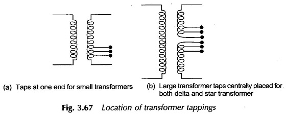
For achieving large voltage variation, tappings should be placed near the centres of the phase windings to reduce magnetic asymmetry. However, this arrangement cannot be put on LV windings placed next to the core (as in core type transformer) because of accessibility and insulation considerations. The HV winding placed outside the LV winding is easily accessible and can, thus, be tapped easily.
It is not possible to tap other than an integral number of turns and this may not be feasible with LV side tappings. For example 250 V phase winding with 15 V/turn cannot be tapped closer than 5%. It is therefore essential to tap the HV windings which is advantageous in a step-down transformer.
Some of the methods of locating tappings are depicted in Fig. 3.67(a) and (b).
Axial mmf unbalance is minimized by thinning out the LV winding or by arranging parts of the winding more symmetrically. For very large tapping ranges a special tapping coil may be employed.
Tap Changing Transformer causes changes in leakage reactance, core loss, I2R loss and perhaps some problems in parallel operation of dissimilar transformers.
Off Load Tap Changer or Off Circuit or No Load Tap Changer:
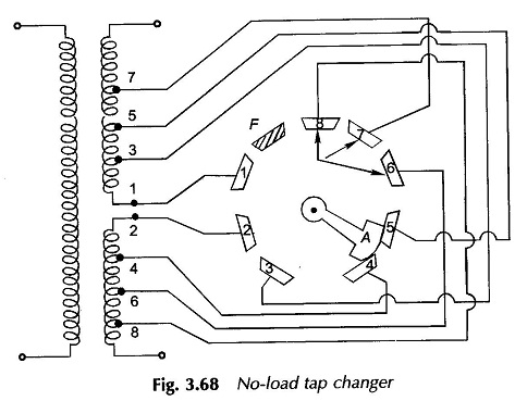
The cheapest method of changing the turn ratio of a transformer is the use of Off Load Tap Changer. As the name indicates, it is required to deenergize the transformer before changing the tap. A simple Off Load Tap Changer is shown in Fig. 3.68. It has eight studs marked one to eight. The winding is tapped at eight points. The face plate carrying the suitable studs can be mounted at a convenient place on the transformer such as upper yoke or located near the tapped positions on the windings. The movable contact arm A may be rotated by handwheel mounted externally on the tank.
If the winding is tapped at 2% intervals, then as the rotatable arm A is moved over to studs 1, 2; 2, 3; . . . 6, 7; 7, 8 the winding in circuit reduces progressively by it from 100% with arm at studs (1, 2) to 88% at studs (7, 8).
The stop F which fixes the final position of the arm A prevents further anticlockwise rotation so that stud 1 and 8 cannot be bridged by the arm. Adjustment of tap setting is carried out with transformer deenergized. For example, for 94% tap the arm is brought in position to bridge studs 4 and 5. The transformer can then be switched on.
To prevent unauthorized operation of an off-circuit tap changer, a mechanical lock is provided. Further, to prevent inadvertent operation, an electromagnetic latching device or microswitch is provided to open the circuit breaker so as to deenergize the transformer as soon as the tap changer handle is moved; well before the contact of the arm with the stud (with which it was in contact) opens.
On Load Tap Changing Transformer:
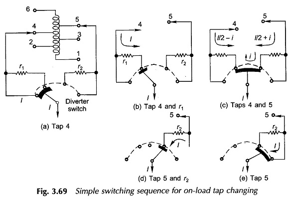
On Load Tap Changing Transformer are used to change the turn ratio of transformer to regulate system voltage while the transformer is delivering load. With the introduction of On Load Tap Changing Transformer, the operating efficiency of electrical system gets considerably improved. Nowadays almost all the large power transformers are fitted with on load tap changer. During the operation of an on load tap changer the main circuit should not be opened to prevent (dangerous) sparking and no part of the tapped winding should get short-circuited. All forms of on load tap changer circuits are provided with an impedance, which is introduced to limit short-circuit current during the tap changing operation. The impedance can either be a resistor or centre-tapped reactor. The On Load Tap Changing Transformer can in general be classified as resistor or reactor type. In modem designs the current limiting is almost invariably carried out by a pair of resistors.
On Load Tap Changing Transformer gear with resistor transition, in which one winding tap is changed over for each operating position, is depicted in Fig. 3.69. The figure also shows the sequence of operations during the transition from one tap to the next (adjoining) (in this case from tap 4 to tap 5). Back-up main contractors are provided which short-circuit the resistor for normal operation.
To ensure that the transition once started gets completed, an energy (usually a spring device) storage is provided which acts even if the auxiliary power supply happens to fail. In resistor-aided Tap Changing Transformer the current break is made easier by the fact that the short-circuit resistor causes the current to be opened to have unity power factor.
On Load Tap Changer control gear can be from simple push-button initiation to complex automatic control of several transformers operating in parallel. The aim is to maintain a given voltage level within a specified tolerance or to raise it with load to compensate for the transmission line voltage drop. The main components are an automatic voltage regulator, a time delay relay, and compounding elements. The time delay prevents unwanted initiation of a tap change by a small transient voltage fluctuation. It may be set for a delay unto 1 min.
At present tap changers are available for the highest insulation level of 1475 kV (peak) impulse and 630 kV power frequency voltage. Efforts are underway to develop tap changers suitable for still higher insulation levels. More compact tap changers with high reliability and performance are being made by employing vacuum switches in the diverter switch. Also, now thyristorized tap changers are available for special applications where a large number of operations are desired.


