Switching Regulator Operation:
A Switching Regulator Operation can be thought of as similar to a linear regulator, but with the series-pass transistor operating as a switch that is either off, or switched on (in a saturated state). The output voltage from the switch is a pulse waveform which is smoothed into a dc voltage by the action of an LC filter.
Switching Regulator Operation can be classified as:
- step-down converter (output voltage lower than input)
- step-up converter (output higher than input)
- inverting converter (output polarity opposite to input)
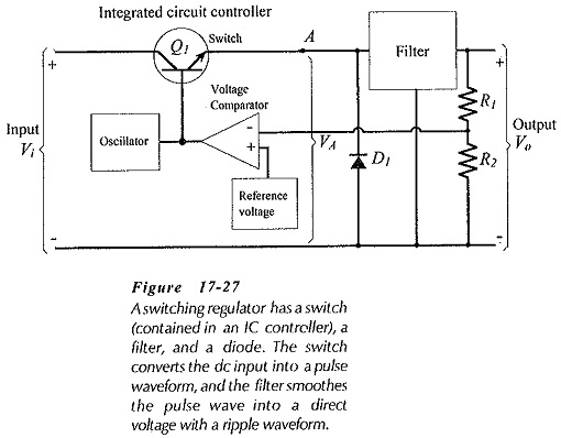
The basic block diagram of a step-down Switching Regulator Operation in Fig. 17-27 consists of a transistor switch (Q1) (also termed a power switch), an oscillator, a voltage comparator, a voltage reference source, a diode (D1), and a filter. The switch, oscillator, comparator, and reference source are all usually contained within an integrated circuit controller, as illustrated. The filter usually consists of an inductor and capacitor.
The operation of the regulator is as follows:
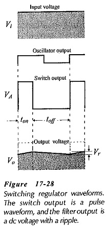
- The dc input voltage (Vi) is converted into a pulse waveform (VA) by the action of the switch (Q1) turning on and off. This is illustrated by the waveforms in Fig. 17-28.
- The oscillator switches Q1 on, causing current to flow to the filter, and the output voltage to rise.
- The voltage comparator compares the output voltage (divided by R1 and R2) to the reference voltage, and it holds Q1 on until Vo equals Vref. Then, Q1 is turned off again.
- The pulse waveform (VA) at, the filter input is produced by Q1 turning on and off.
- The filter smoothes the pulse waveform to produce a dc output voltage (Vo) with a ripple waveform (Vr).
- The ripple waveform is the result of the filter capacitor charging via the filter inductor during ton, and then discharging to the load during toff via D1.
In the operation described above, the controller can be thought of as a pulse width modulator; the on time of Q1 (pulse width of its output) is increased or decreased as necessary to supply the required output current. Other systems involve control of the switch off time.
Comparison of Linear and Switching Regulators:
The power dissipated in the series-pass transistor in a linear regulator is wasted power. This is not very important when the load current is lower than 500 mA. With high current levels, the regulator efficiency becomes important, and there can also be serious heat dissipation problems.
In a Switching Regulator Operation, the power dissipation in the switching transistor (whether it is on or off) is very much smaller than in the series-pass transistor of a linear regulator with a similar output voltage and load current. So, a switching regulator is more efficient than a linear regulator.
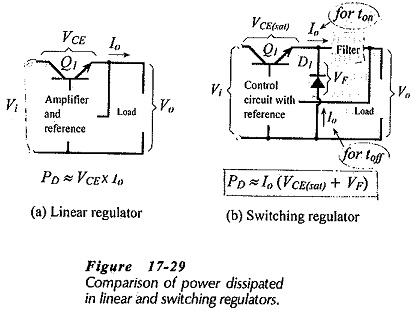
The approximate efficiency of a linear regulator can be calculated by assuming that the only wasted power (PD) is that dissipated in the series-pass transistor, [see Fig. 17-29(a)].
![]()
To estimate the efficiency of a switching regulator, it should be noted that D1 (in Fig. 17-27) is biased off when Q1 is on and that D1 is on when Q1 is off. So, the power dissipated in the switching transistor and diode can be taken as the total wasted power, [Fig. 17-29(b)]. The Q1 and D1 power dissipation can be calculated in terms of the actual current level in each device and the on and off times. This analysis shows that PD for each device, is simply [(average output current) x (device voltage drop)). So,
![]()
As discussed, there is much less power dissipation in the transistor and diode in a Switching Regulator Operation than in the series-pass transistor of a linear regulator with the same output conditions. So, a lower power transistor can be used in the switching regulator. Also, with a switching regulator there is usually no need for the heat sink normally required with a series regulator.
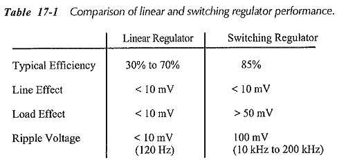
As well as efficiency, there are other considerations in the choice between linear and switching regulators. The output ripple voltage with a switching regulator is substantially larger than with a linear regulator. The line effect can be similar with both types of regulator, but the load effect is usually largest with a switching regulator. For low levels of output power, a Switching Regulator Operation is usually more expensive than a linear regulator. A linear regulator is usually the best choice for output power levels up to 10 W. A switching regulator should be considered when the output is above 10 W. Table 17-1 compares the two voltage regulator types.