Booster Generator:
A Booster Generator is a D.C. generator whose function is to inject or add certain voltage into a circuit so as to compensate the IR drop in the feeders etc.
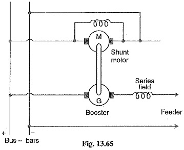
A Booster Generatorr is essentially a series d.c. generator of large current capacity and is connected in series with the feeder whose voltage drop is to be compensated as shown in Fig.13.65. It is driven at constant speed by a shunt motor working from the bus-bars. As the booster is a series generator, therefore, voltage generated by it is directly proportional to the field cunent which is here the feeder current. When the feeder current increases, the voltage drop in the feeder also increases. But increased feeder current results in greater field excitation of Booster Generator which injects higher voltage into the feeder to compensate the voltage drop. For exact compensation of voltage drop, the Booster Generator must be marked on the straight or linear portion of its voltage-current characteristics.
It might be suggested to compensate the voltage drop in the feeder by over compounding the generators instead of using a booster. Such a method is not practicable for feeders of different lengths because it will disturb the voltage of other feeders. The advantage of using a Booster Generator is that each feeder can be regulated independently a great advantage if the feeders are of different lengths.
Comparison of Three Wire and Two Wire DC Distribution:
It is worthwhile to make a comparison between Three Wire and Two Wire DC Distribution. It will be shown that there is a great saving of conductor material if we use 3-wire system instead of 2-wire system for d.c. distribution. For comparison, it will be assumed that
- the amount of power P transmitted is the same
- the voltage Vat the consumer’s terminals is the same
- the distance of transmission is the same
- the efficiency of transmission (and hence losses) is the same
- the 3-wire system is balanced e. no current in the neutral wire
- the area of X-section of neutral wire is half the cross-section of outers in 3-wire system

Current through outers in case of 3-wire system is
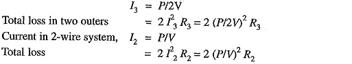
Since efficiency of transmission is the same, it means losses are the same i.e.
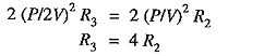
Therefore the area of X-section of outers in 3-wire case will be one-fourth of each conductor in 2-wire case.
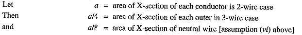
If l is the length of the line, then,
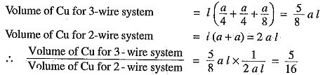
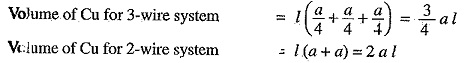
Hence a 3-wire system requires only 5/16 th (or 31.25%) as much copper as a 2-wire system. If the neutral has the same X-section as the outer, then,
Ground Detectors:
Ground detectors are the devices that are used to detect/indicate the ground fault for ungrounded d.c. systems. When a ground fault occurs on such a system, immediate steps should be taken to clear it. If this is not done and a second ground fault happens, a short circuit occurs. Lamps are generally used for the detection of ground faults. They are connected for ungrounded 2-wire system as shown in Fig. 13.66.
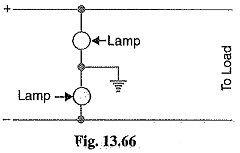
Each lamp should have a voltage rating equal to the line voltage. The two lamps in series, being subjected to half their rated voltage, will glow dimly. If a ground fault occurs on either wires, the lamp connected to the grounded wire will not glow while the other lamp will glow brightly.