Selection of Electric Drive:
For selection of electric drive motor it is essential that the conditions of service are well known. It is not sufficient to simply specify the output power in kW and the speed but it is also necessary to know the following additional particulars :
- Torque at the shaft during running, starting and at different loads.
- Accelerating torque and braking torque.
- Switching frequency.
- Efficiency of motor at different loads.
- Other working requirements.
In studying the behavior of a selection of electric drive unit, one of the first problems involved is to determine whether the speed-torque characteristic of the motor suits the requirements imposed by the speed-torque characteristic of the driven unit. Selection of electric drive behavior during the transient period of a start-up, braking, or speed change-over also depends upon how the speed-torque characteristics of the motor and the driven unit vary with speed. It is, therefore, imperative to study these characteristics in order to be able to select correctly the motor and obtain an economical drive.
1. Speed-Torque Characteristics of Machines or Mechanisms
The speed-torque characteristic of a machine or mechanism given by the relation ω = f(TL) is defined as the relationship between the speed at which it is operated and the resisting or load torque it develops.
Different kinds of mechanisms and machines exhibit different speed-torque characteristics. However, several general conclusions may be drawn if we use the following empirical equation for the speed-torque characteristic of some driven unit of industrial equipment
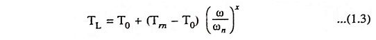
where TL is gross load (or resisting) torque developed by the unit at speed ω, T0 is the resisting torque developed by the unit due to friction in its moving parts, Tm is the resisting torque developed by the unit when it is driven at its nominal rated speed ωn and x is the exponential coefficient characterizing the change in resisting torque with the change in speed.
The above Eq. (1.3) permits the speed-torque characteristics of different kinds of machines and mechanisms to be roughly divided into the following categories :
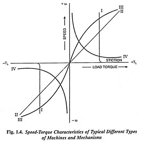
1. Loads Requiring Constant Torque at All Speeds: Such a load presents to the motor a passive torque which is essentially independent of speed. It is characterized also by the requirement of an extra torque at very near zero speed. For this characteristic x = 0 and the load torque TL does not depend upon speed. The speed-torque characteristic for such loads is illustrated by vertical line in Fig. 1.4. Such loads are dry friction, cranes during hoisting, hoist winches, machine tool feed mechanism, piston pumps operating against a constant pressure head, and conveyors handling a constant weight of material per unit time. In power applications it is usually called the breakaway torque and in control systems, it is referred to as stiction (derived from sticking friction).
Since it changes sign with reversal of rotation, the dry friction torque characteristic is discontinuous, as illustrated in Fig. 1.4.
2. Loads With Linear-Rising Characteristic: Such speed-torque characteristics, illustrated by straight line II in Fig. 1.4, are exhibited by calendering machines, eddy current brakes, separately excited dc generators supplying fixed ohmic resistance loads and fluid or viscous friction. In this case x = 1 and the load torque TL rises in direct proportion to the speed.
3. Loads With Non-Linear-Rising (Parabolic) Characteristic: For such a characteristic x = 2 and the load torque TL is proportional to the square of the speed. Such a characteristic is illustrated by curve III in Fig. 1.4. A load with considerable windage, of which a fan is the extreme example, has a torque which varies almost as the square of the speed. Blowers, centrifugal pumps, propellers in ships or aeroplanes, water wheels, pipe friction, velocity head of pumps etc. also have the same type of speed-torque characteristics.
4. Loads With Non-Linear Falling (Hyperbolic) Characteristic (or Constant Power Load): For such a characteristic x = – 1 and the load torque TL is inversely proportional to the speed, while the power required to drive the given unit remains unchanged. Such a characteristic is illustrated by curve IV in Fig. 1.4. Certain types of lathes, boring machines, milling machines and other kinds of metal-cutting machine tools, steel-mill coilers fall under this category of loads.
The categories of loads listed above do not cover all the cases that may be met with in practice but give a good idea of the characteristics typical of a great many kinds of industrial equipment. In actual practice we may come across loads which are combination of these basic types of loads.
2. Load Torque-Time Characteristics:
Perhaps, the variation of load torque with time is of equal or greater importance in selection of electric drive. This variation in certain applications, can be periodic and repetitive, one cycle of variation being called a duty cycle. Different types of loads from the point of view of load torque characteristics, may be classified as follows.
(i) Continuous, constant loads such as paper making machines, centrifugal pumps or fans operating for a long time under the same conditions.
(ii) Continuous, variable loads such as hoisting winches, metal-cutting lathes, conveyors etc.
(iii) Pulsating loads such as reciprocating pumps and textile looms and, in general, all machines having crank shaft.
(iv) Impact load such as rolling mills, shearing machines, presses, forging hammers etc. Apparent, regular and repetitive load peaks or pulses occur in such loads.
(v) Short time loads such as motor-generator sets for charging of batteries; servo-motors used in remote control of drilling machine clamping rods.
(vi) Short time intermittent loads such as cranes and hoisting mechanisms, excavators, roll trains etc.
Certain machines (such as ball mills) do not strictly belong to any category mentioned above. If such loads (ball mills, stone crushers etc.) were characterized by frequent impacts of comparatively small peaks, it would be more appropriate to place them in the category of continuous variable loads rather than impact loads. Sometimes, it is quite cumbersome to make distinction between pulsating loads and impact loads, because both of them are periodic in nature.
One and same drive can be represented by a load torque which varies either with speed or with time. The most appropriate example is a fan load whose load torque TL is proportional to the square of speed, is also a continuous constant load.
3. Load Torques Varying With Shaft Displacement Angle:
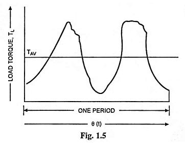
In all machines having crankshafts, such as reciprocating pumps and compressors, frame-saws etc. load torque varies with the angular displacement of the shaft or rotor of the motor. For all such machines, the load torque TL can be resolved into two components—one of constant magnitude Tav and the other a variable T′L which changes periodically in magnitude depending on the angular position of the shaft. Such load torque characteristics, can, for simplicity, be represented by a Fourier series as a sum of oscillations of fundamental and harmonic frequencies, i.e.,
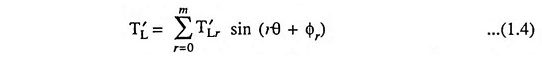
where θ = ωt, ω being the angular speed of the motor shaft driving the compressor.
During variations in speed, only small deviations from a fixed value of speed ωa occur, therefore, displacement can be represented by θ = (ωa + Δω)t. Thus the variable portion of the load torque may be given as
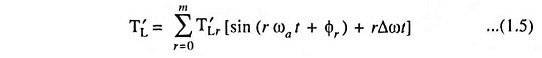
The term rΔωt being very small in magnitude may be neglected. Thus, restricting to small deviations in angle from the equilibrium position, a load torque varying with angular displacement of shaft can be transformed to one which varies periodically w.r.t. time.
4. Load Torques Depending on Path or Position of Load During Motion:
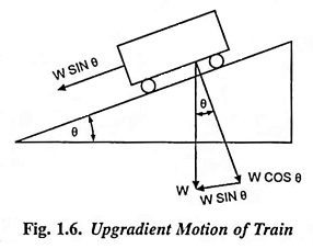
In earlier article, load torques varying with speed were considered. However, load torques, that depend not only speed but also on the nature of the path traced out by the load during its motion, do exist both in hoisting mechanisms and transport systems. For example, the resistance to motion of a train moving upgradient or taking a turn depends on the magnitude of the gradient or the radius of curvature of the track respectively.
Force due to the gradient is given as
![]()
where
- W is the weight of train in tonne.
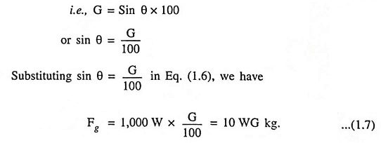
But in railway work gradient is expressed as rise in metres in a track distance of 100 m, and is denoted by ‘percentage gradient’ (G%)
The tractive force required to overcome curvature resistance is given by the empirical formula given below

where
- R is the radius of curvature in metres.
In hoisting mechanisms in which tail ropes or balancing ropes are not employed (Fig. 1.7), the load torque is not only due to the weight of the unloaded or the loaded cage but also due to that of the lifting ropes or cables, which depends on the position of two cages. When cage 1 is at the bottom most position and is to be lifted upwards, the entire weight of the rope is also to he moved up. When both the cages are at the same height, the weight of the rope to be lifted becomes zero, since the weight of the ropes on both sides balance each other, being equal in length. When cage 1 is at a higher position than cage 2, a portion of the weight of the rope acts in such a way as to assist the upward motion of the cage 1. Ultimately when cage 1 reaches the top most position. the whole weight of the rope assists the upward movement.
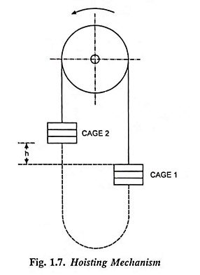
The force resisting the upward movement of the load, Fr due to varying weight of the rope depending on the position of the load is given as

where
- Wr is the total weight of the rope in kg,
- h is the desired maximum height to which the cage is to be moved upwards, in metres and
- x is the height of the cage at any arbitrary position from the bottom most position in metres.
For large values of h, the force Fr affects to a large extent, the performance of the drive used in hoisting mechanisms because in such a situation the weight of the rope may be considerably larger than that of the load to be lifted upwards. If we use tail ropes, as illustrated by means of dotted lines in Fig. 1.7, the weight of the connecting rope can be balanced and almost smooth movement of the cages can be had.