Fixed Bias Circuit Diagram – Advantages and Disadvantages
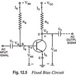
Fixed Bias Circuit Diagram - Advantages and Disadvantages: Fixed Bias Circuit Diagram shown in Fig. 12.5 uses two batteries VBB and VCC. The battery VBB gives potential to the base…
Tuned Collector Oscillator - Definition, Working and Equation: The basic circuit of a tuned collector oscillator is shown in Fig. 21.7. It is called the tuned collector oscillator, because the…
Photodetectors - Definition and Applications: Photodetectors are the semiconductor devices that can detect optical signals through electronic processes. The extension of coherent and incoherent light sources into the far-infrared region…
Emitter Coupled Clipper Circuit: An emitter coupled clipper using two transistors is shown in Fig. 30.71. It is a two level clipper in which the input is applied to the…
What is Clipper Circuit? - Definition and Classification Clipper Circuit is one which controls the shape of the waveform by removing or "clipping" off an unwanted portion. A half-wave rectifier…
Integrated Injection Logic (IIL or I2L) Circuit: It is the latest entry into the bipolar saturated logic field. It uses no biasing and loading resistors at all. Resistors require lot…
Thyristor in Static Relay: The structure of Thyristor in Static Relay consists of four alternate p-and n-type layers. In the thyristor (also called a silicon controlled rectifier—SCR) connections are made…
BJT Power Amplifier with Op Amp Driver: BJT Power Amplifier with Op Amp Driver Circuit Operation - The Class-AB power shown in Fig. 18-39 uses an operational amplifier (A1) for…