FET Equivalent Circuit Model
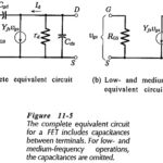
FET Equivalent Circuit Model: The complete FET Equivalent Circuit Model is shown in Fig. 11-5(a). It is seen that tilt source terminal is common to both input and out, so…
Continue Reading
FET Equivalent Circuit Model
FET Equivalent Circuit Model: The complete FET Equivalent Circuit Model is shown in Fig. 11-5(a). It is seen that tilt source terminal is common to both input and out, so…
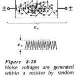
Transistor Circuit Noise: Unwanted signals at the output of an electronics system are termed noise. The noise amplitude may be large enough to severely distort, or completely swamp, the wanted…
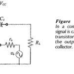
Common Base Circuit Diagram: The Common Base Circuit Diagram (CB) shown in Fig. 6-34 is very similar to a CE circuit, except that the input signal is applied to the…
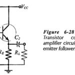
Common Collector Circuit Analysis: In the Common Collector Circuit Analysis (CC) shown in Fig. 6-28 the external load (RL) is capacitor-coupled to the transistor emitter terminal. The circuit uses voltage divider…
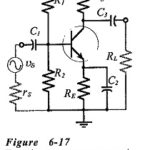
Common Emitter Amplifier Circuit: Consider the Common Emitter Amplifier Circuit circuit shown in Fig. 6-17. When the capacitors are regarded as ac short-circuits, it is seen that the circuit input…
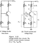
Voltage Divider Bias Circuit: Circuit Operation - Voltage Divider Bias Circuit, also known as emitter current bias, is the most stable of the three basic transistor bias circuits. A voltage…
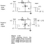
Shunt Clipping Circuits: A positive Shunt Clipping Circuits is illustrated in Fig. 3-28(a). Here the diode is connected in shunt (or parallel) with the output terminals. When the input is…
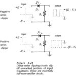
Diode Series Clipper Circuit: The function of a Diode Series Clipper Circuit (or limiter) is to clip off an unwanted portion of a waveform. This is sometimes necessary to protect…