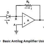
Basic Antilog Amplifier Using Diode
Basic Antilog Amplifier Using Diode: The circuit diagram of basic antilog amplifier using diode is shown in the Fig. 2.70. The positions of diode and resistance are exchanged as compared…
Continue Reading
Basic Antilog Amplifier Using Diode