Power System Components Articles:
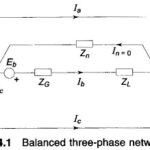
Balanced Three Phase Circuit: The solution of a balanced three phase circuit is easily carried out by solving the single-phase network corresponding to the reference phase. Figure 4.1 shows a simple, balanced three phase circuit. The generator and load neutrals are therefore … (Read More)
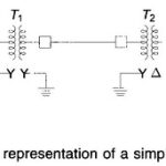
Single Line Diagram of Power System and Impedance or Reactance Diagram: A single line diagram of power system shows the main connections and arrangements of components. Any particular component may or may not be shown depending on the information required in … (Read More)
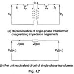
Per Unit System in Power System: Per Unit System in power system is usual to express voltage, current, voltamperes and impedance of an electrical circuit in per unit (or percentage) of base or reference values of these quantities. The per unit … (Read More)
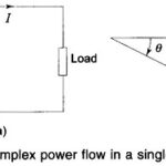
Complex Power Flow in a Single Phase Load: Here we are going to discuss about complex power flow in a single phase load. Consider a single phase load fed from a source as in Fig. 4.9. Let When θ is positive, the … (Read More)
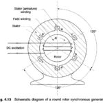
Phasor Diagram of Synchronous Motor: The Phasor Diagram of Synchronous Motor is the most important element of a power system. It converts mechanical power into electrical form and feeds it into the power network or, in the case of a motor, … (Read More)
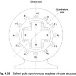
Salient Pole Synchronous Generator: A Salient Pole Synchronous Generator, as shown in Fig. 4.29, is distinguished from a round rotor machine by constructional features of field poles which project with a large interpolar air gap. This type of construction is commonly … (Read More)
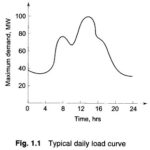
What is Load Curve?: Load drawn by consumers is the toughest parameter to assess scientifically. The magnitude of the load, in fact, changes continuously so that the load forecasting problem is truly a statistical one. A typical daily Representation of Load … (Read More)