Equal Area Criterion in Power System:
In a system where one machine is swinging with respect to an infinite bus, it is possible to study transient stability by means of a simple Equal Area Criterion in Power System, without resorting to the numerical solution of a swing equation.
Consider the swing equation

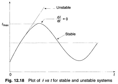
If the system is unstable δ continues to increase indefinitely with time and the machine loses synchronism. On the other hand, if the system is stable, δ(t) performs oscillations (nonsinusoidal) whose amplitude decreases in actual practice because of damping terms (not included in the swing equation). These two situations are shown in Fig. 12.18. Since the system is non-linear, the nature of its response [δ(t)] is not unique and it may exhibit instability in a fashion different from that indicated in Fig. 12.18, depending upon the nature and severity of disturbance. However, experience indicates that the response δ(t) in a power system generally falls in the two broad categories as shown in the figure. It can easily be visualized now (this has also been stated earlier) that for a stable system, indication of stability will be given by observation of the first swing where δ will go to a maximum and will start to reduce. This fact can be stated as a stability criterion, that the system is stable if at some time
![]()
and is unstable, if
![]()
for a sufficiently long time (more than 1 s will generally do).
The stability criterion for power systems stated above can be converted into a simple and easily applicable form for a single machine infinite bus system.
Multiplying both sides of the swing equation by (2 dδ/dt), we get
![]()
Integrating, we have
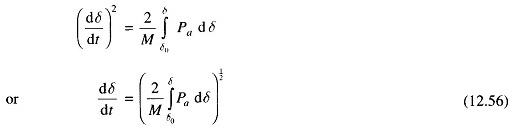
where δ0 is the initial rotor angle before it begins to swing due to disturbance.
From Eqs. (12.55) and (12.56), the condition for stability can be written as
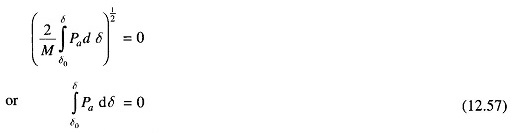
or
The condition of stability can therefore be stated as: the system is stable if the area under Pa (accelerating power) – δ curve reduces to zero at some value of δ. In other words, the positive (accelerating) area under Pa — δ curve must equal the negative (decelerating) area and hence the name ‘equal area’ criterion of stability.
To illustrate the Equal Area Criterion in Power System of stability, we now consider several types of disturbances that may occur in a single machine infinite bus bar system.
Sudden Change in Mechanical Input:
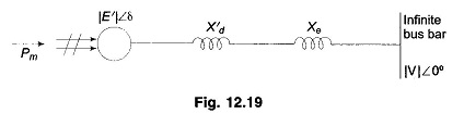
Figure 12.19 shows the transient model of a single machine tied to infinite bus bar. The electrical power transmitted is given by
![]()
Under steady operating condition
![]()
This is indicated by the point a in the Pe – δ diagram of Fig. 12.20.
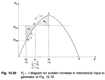
Let the mechanical input to the rotor be suddenly increased to Pm1 (by opening the steam valve). The accelerating power Pa = Pm1 – Pe causes the rotor speed to increase (ω > ωs) and so does the rotor angle. At angle δ1, Pa = Pm1 – Pe (=Pmax sin δ1) = 0 (state point at b) but the rotor angle continues to increase as ω > ωs. Pa now becomes negative (decelerating), the rotor speed begins to reduce but the angle continues to increase till at angle δ2, ω = ωs once again (state point at c. At c), the decelerating area A2 equals the accelerating area A1 (areas are shaded), i.e.,

Since the rotor is decelerating, the speed reduces below ωs and the rotor angle begins to reduce. The state point now traverses the Pe – δ curve in the opposite direction as indicated by arrows in Fig. 12.20. It is easily seen that the system oscillates about the new steady state point b (δ = δ1) with angle excursion up to δ0 and δ2 on the two sides. These oscillations are similar to the simple harmonic motion of an inertia-spring system except that these are not sinusoidal.
As the oscillations decay out because of inherent system damping (not modelled), the system settles to the new steady state where
![]()
From Fig. 12.20, areas A1 and A2 are given by
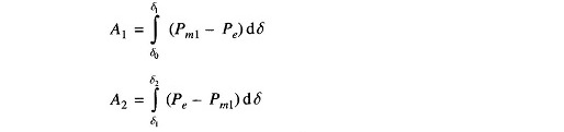
For the system to be stable, it should be possible to find angle δ2 such that A1 = A2. As Pm1 is increased, a limiting condition is finally reached when A1 equals the area above the Pm1 line as shown in Fig. 12.21. Under this condition, δ2 acquires the maximum value such that
![]()
Any further increase in Pm1 means that the area available for A2 is less than A1, so that the excess kinetic energy causes δ to increase beyond point c and the decelerating power changes over to accelerating power, with the system consequently becoming unstable. It has thus been shown by use of the Equal Area Criterion in Power System that there is an upper limit to sudden increase in mechanical input (Pm1 – Pm0) for the system in question to remain stable.
It may also be noted from Fig. 12.21 that the system will remain stable even though the rotor may oscillate beyond δ = 90°, so long as the Equal Area Criterion in Power System is met. The condition of δ = 90° is meant for use in steady state stability only and does not apply to the transient stability case.
Effect of Clearing Time on Stability:
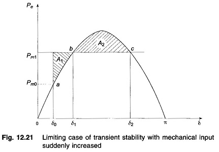
Let the system of Fig. 12.22 be operating with mechanical input Pm at a steady angle of δ0 (Pm = Pe) as shown by the point a on the Pe – δ diagram of Fig. 12.23. If a 3-phase fault occurs at the point P of the outgoing radial line, the electrical output of the generator instantly reduces to zero, i.e., Pe = 0 and the state point drops to b. The acceleration area A1 begins to increase and so does the rotor angle while the state point moves along bc. At time tc corresponding to angle δc the faulted line is cleared by the opening of the line circuit breaker. The values of tc and δc are respectively known as clearing time and clearing angle. The system once again becomes healthy and transmits Pe = Pmax sin δ i.e. the state point shifts to d on the original Pe – δ curve. The rotor now decelerates and the decelerating area A2 begins while the state point moves along de.
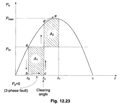
If an angle δ1 can be found such that A2 = A1, the system is found to be stable. The system finally settles down to the steady operating point a in an oscillatory manner because of inherent damping.
The value of clearing time corresponding to a clearing angle can be established only by numerical integration except in this simple case. The Equal Area Criterion in Power System therefore gives only qualitative answer to system stability as the time when the breaker should be opened is hard to establish.
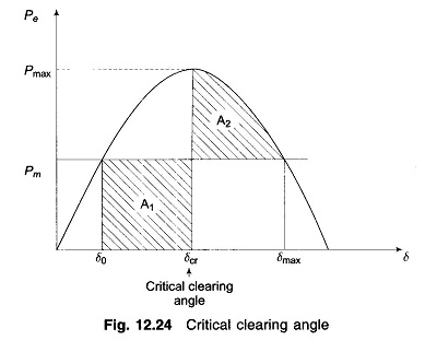
As the clearing of the faulty line is delayed, A1 increases and so does δ1 to find A2 = A1 till δ1 = δmax as shown in Fig. 12.24. For a clearing time (or angle) larger than this value, the system would be unstable as A2 < A1. The maximum allowable value of the clearing time and angle for the system to remain stable are known respectively as critical clearing time and angle.
For this simple case (Pe = 0 during fault), explicit relationships for δc (critical) and tc (critical) are established below. All angles are in radians.
It is easily seen from Fig. 12.24 that
![]()
and
![]()
Now

and

For the system to be stable, A2 = A1, which yields
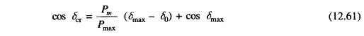
where
- δcr = critical clearing angle
Substituting Eqs. (12.59) and (12.60) in Eq. (12.61), we get
![]()
During the period the fault is persisting, the swing equation is
![]()
Integrating twice
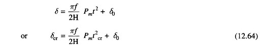
where
- tcr = critical clearing time
- δcr = critical clearing angle
From Eq. (12.64)

where δcr is given by the expression of Eq. (12.62)
An explicit relationship for determining tcr is possible in this case as during the faulted condition Pe = 0 and so the swing equation can be integrated in closed form. This will not be the case in most other situations.
Sudden Loss of One of Parallel Lines:
Consider now a single machine tied to infinite bus through two parallel lines as in Fig. 12.25a. Circuit model of the system is given in Fig. 12.25b.
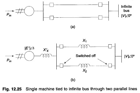
Let us study the transient stability of the system when one of the lines is suddenly switched off with the system operating at a steady load. Before switching off, power angle curve is given by
![]()
Immediately on switching off line 2, power angle curve is given by

Both these curves are plotted in Fig. 12.26, wherein PmaxII < PmaxI as (X′d+X1) > (X′d+X1 II X2). The system is operating initially with a steady power transfer Pe = Pm at a torque angle δ0 on curve I.
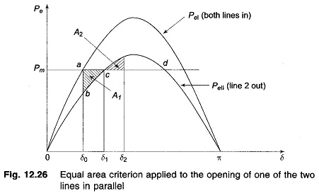
Immediately on switching off line 2, the electrical operating point shifts to curve II (point b). Accelerating energy corresponding to area A1 is put into rotor followed by decelerating energy for δ > δ1. Assuming that an area A2 corresponding to decelerating energy (energy out of rotor) can be found such that A1 = A2, the system will be stable and will finally operate at c corresponding to a new rotor angle δ1 > δ0. This is so because a single line offers larger reactance and larger rotor angle is needed to transfer the same steady power.
It is also easy to see that if the steady load is increased (line Pm is shifted upwards in Fig. 12.26), a limit is finally reached beyond which decelerating area equal to A1 cannot be found and therefore, the system behaves as an unstable one. For the limiting case of stability, δ1 has a maximum value given by
![]()
which is the same condition as in the previous example.
Sudden Short Circuit on One of Parallel Lines:
Case a: Short circuit at one end of line
Let us now assume the disturbance to be a short circuit at the generator end of line 2 of a double circuit line as shown in Fig. 12.27a. We shall assume the fault to be a three-phase one.
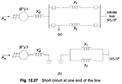
Before the occurrence of a fault, the power angle curve is given by

which is plotted in Fig. 12.25.
Upon occurrence of a three-phase fault at the generator end of line 2 (see Fig. 12.24a), the generator gets isolated from the power system for purposes of power flow as shown by Fig. 12.27b. Thus during the period the fault lasts,
![]()
The rotor therefore accelerates and angles δ increases. Synchronism will be lost unless the fault is cleared in time.
The circuit breakers at the two ends of the faulted line open at time tc (corresponding to angle δc), the clearing time, disconnecting the faulted line.
The power flow is now restored via the healthy line (through higher line reactance X2 in place of X1 || X2), with power angle curve

Obviously, Pmax|| < Pmax|. The rotor now starts to decelerate as shown in Fig. 12.28. The system will be stable if a decelerating area A2 can be found equal to accelerating area A1 before δ reaches the maximum allowable value δmax. As area A1 depends upon clearing time tc (corresponding to clearing angle δc), clearing time must be less than a certain value (critical clearing time) for the system to be stable. It is to be observed that the Equal Area Criterion in Power System helps to determine critical clearing angle and not critical clearing time. Critical clearing time can be obtained by numerical solution of the swing equation.
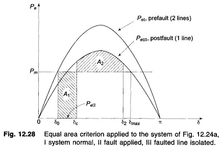
It also easily follows that larger initial loading (Pm) increases A1 for a given clearing angle (and time) and therefore quicker fault clearing would be needed to maintain stable operation.
Case b: Short circuit away from line ends
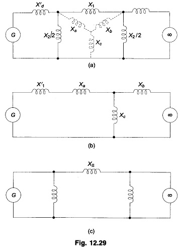
When the fault occurs away from line ends (say in the middle of a line), there is some power flow during the fault though considerably reduced, as different from case a where PeII = 0. Circuit model of the system during fault is now shown in Fig. 12.29a. This circuit reduces to that of Fig. 12.29c through one delta-star and one star-delta conversion. The power angle curve during fault is therefore given by

PeI and PeIII as in Fig. 12.28 and PeII as obtained above are all plotted in Fig. 12.30. Accelerating area A1 corresponding to a given clearing angle δc is less
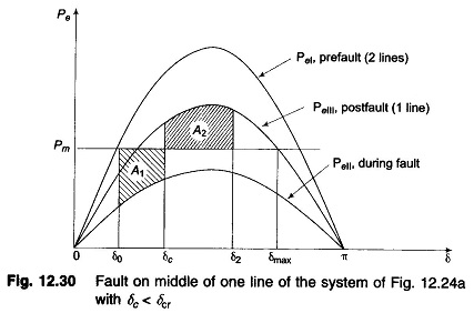
in this case, than in case a, giving a better chance for stable operation. Stable system operation is shown in Fig. 12.30, wherein it is possible to find an area A2 equal to A1 for δ2 < δmax. As the clearing angle δc is increased, area A1 increases and to find A2 = A1, δ2 increases till it has a value δmax, the maximum allowable for stability. This case of critical clearing angle is shown in Fig. 12.31.
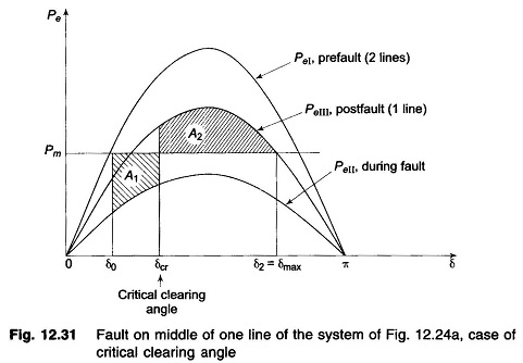
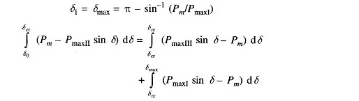
Applying Equal Area Criterion in Power System to the case of critical clearing angle of Fig. 12.31,
we can write

where

Integrating, we get

or

or

Critical clearing angle can be calculated from Eq. (12.67) above. The angles in this equation are in radians. The equation modifies as below if the angles are in degrees.

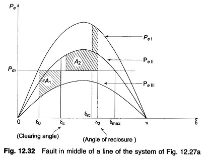
Case c: Reclosure
If the circuit breakers of line 2 are reclosed successfully (i.e., the fault was a transient one and therefore vanished on clearing the faulty line), the power transfer once again becomes
![]()
Since reclosure restores power transfer, the chances of stable operation improve. A case of stable operation is indicated by Fig. 12.32.
For critical clearing angle
where trc = tcr + τ; τ = time between clearing and reclosure.