Transformers

Transformer Nameplate Rating

Transformer Nameplate Rating: Transformer Nameplate Rating Details – The voltage ratio is specified as V1 (rated)/V2 (rated). It means that when voltage V1 (rated) is applied to the primary, the secondary voltage on full load at specified pf is V2 (rated). The ratio V1 (rated)/V2 (rated) is not exactly equal to N1/N2, because of voltage […]

Transformer Nameplate Rating Read More »

Phasor Diagram of Transformer

Approximate Equivalent Circuit

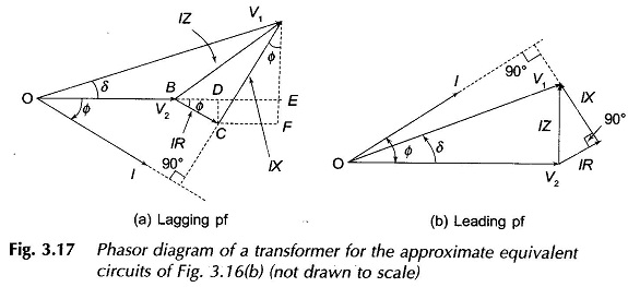
Phasor Diagram of Transformer: For the approximate equivalent circuit of Phasor Diagram of Transformer is shown in Fig. 3.16(b) The phasor diagram corresponding to this equation is drawn in Fig. 3.17(a) for the lagging power factor (phase angle Φ between V2 and I) and in Fig. 3.17(b) for the leading power factor (pf). It is

Phasor Diagram of Transformer Read More »

Approximate Equivalent Circuit of Transformer

Approximate Equivalent Circuit

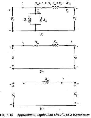
Approximate Equivalent Circuit of Transformer: Approximate Equivalent Circuit of Transformer – In constant frequency (50 Hz) power transformers, approximate forms of the exact T-circuit equivalent of the transformer are commonly used. With reference to Fig. 3.14(c), it is immediately observed that since winding resistances and leakage reactances are very small, V1 ≈ E1 even under conditions

Approximate Equivalent Circuit of Transformer Read More »

Real Transformer On Load Condition

Transformer and Equivalent Circuit

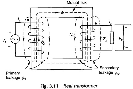
Real Transformer On Load Condition | Equivalent Circuit: Figure 3.11 shows a Real Transformer On Load Condition. Both the primary and secondary have finite resistances R1 and R2 which are uniformly spread throughout the winding; these give rise to associated copper (I2R) losses. While a major part of the total flux is confined to the

Real Transformer On Load Condition Read More »

Ideal Transformer on Load

Ideal Transformer

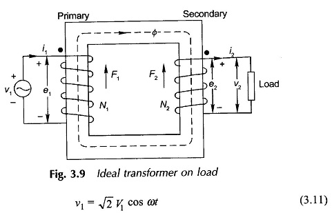
Ideal Transformer on Load: In order to visualize the effect of flow of secondary current in a transformer, certain idealizing assumptions will be made which are close approximations for a practical transformer. A transformer possessing these ideal properties is hypothetical (has no real existence) and is referred to as the Ideal Transformer on Load. It

Ideal Transformer on Load Read More »

Forced Cooling in Transformer

Forced Cooling

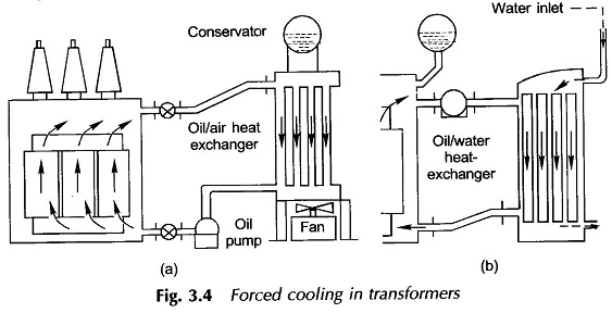
Forced Cooling in Transformer: Forced Cooling in Transformer – For transformer sizes beyond 5 MVA additional cooling would be needed which is achieved by supplementing the tank surface by a separate radiator in which oil is circulated by means of a pump. For better cooling oil-to-air heat exchanger unit is provided as shown in Fig.

Forced Cooling in Transformer Read More »

Transformer Cooling System

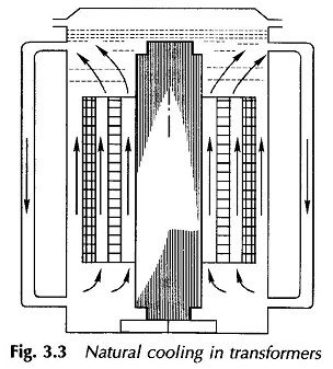
Transformer Cooling System: Transformer Cooling System (Large Units) – Basically, there are two seats of losses in a transformer namely: Core, where eddy current and hysteresis losses occur (caused by alternating density). Windings (primary and secondary) where I2R or copper loss occurs because of the current flowing in these. Heat due to losses must be

Transformer Cooling System Read More »

Scroll to Top