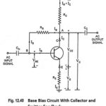
Collector to Base Bias Circuit
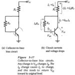
Collector to Base Bias Circuit: The Collector to Base Bias Circuit shown in Fig. 5-17(a) has the base resistor (RB) connected between the transistor collector and base terminals. As will…
Continue Reading
Collector to Base Bias Circuit