Base Bias in BJT
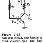
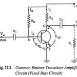
Base Bias in BJT: Circuit Operation and Analysis - The transistor bias arrangement shown in Fig. 5-12 is known as Base Bias in BJT and also as fixed current bias.…
Continue Reading
Base Bias in BJT
Base Bias in BJT: Circuit Operation and Analysis - The transistor bias arrangement shown in Fig. 5-12 is known as Base Bias in BJT and also as fixed current bias.…
BJT Transistor Articles: Transistor Construction: The transistor construction consists of a silicon or germanium (preferably silicon because of its smaller cutoff current ICBO, smaller variations in ICBO due to variations…
Bipolar Junction Transistors (BJTs) Interview Questions and Answers: 1. Explain why BJT is a polar device. Ans. Since both of the charge carriers (electrons and well as holes) are involved in…
Transistor Biasing and Stabilization Interview Questions and Answers: 1. Explain the term biasing. Ans. The proper flow of zero signal collector current and the maintenance of proper collector-emitter voltage during the…
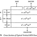
Power BJT - Construction, Operation and its Characteristics: Power transistors are large-area devices. Because of differences in geometry and doping concentrations, their properties tend to vary from those of the…
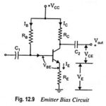
Emitter Bias Circuit Diagram: This Emitter Bias Circuit Diagram is obtained by simply introducing an emitter resistor to the fixed bias circuit as shown in Fig. 12.9. For analysis, we…
Selection of Operating Point in Transistor Biasing: To study the selection of operating point in Transistor biasing conditions on the performance of a transistor, it is necessary to draw a…
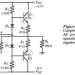
BJT Power Amplifier with Op Amp Driver: BJT Power Amplifier with Op Amp Driver Circuit Operation - The Class-AB power shown in Fig. 18-39 uses an operational amplifier (A1) for…