3 Phase Delta Connection:
Delta Connected System – Figure 9.26 shows a balanced three-phase, three-wire, delta-connected system. This arrangement is referred to as mesh connection because it forms a closed circuit. It is also known as 3 Phase Delta Connection because the three branches in the circuit can also be arranged in the shape of delta (Δ).
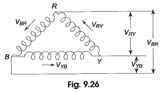
From the manner of interconnection of the three phases in the circuit, it may appear that the three phases are short-circuited among themselves. However, this is not the case. Since the system is balanced, the sum of the three voltages round the closed mesh is zero; consequently, no current can flow around the mesh when the terminals are open.
The arrows placed alongside the voltages, VRY, VYB and VBR, of the three phases indicate that the terminals R, Y and B are positive with respect to Y, B and R, respectively, during their respective positive half cycles.
Voltage Relation:
From Fig. 9.27, we notice that only one phase is connected between any two lines. Hence, the voltage between any two lines (VL) is equal to the phase voltage (VPh).
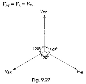
Since the system is balanced, all the phase voltages are equal, but displaced by 120° from one another as shown in the phasor diagram in Fig. 9.27. The phase sequence RYB is assumed.
![]()
Current Relation:
In Fig. 9.28 we notice that, since the system is balanced, the three phase currents (IPh), i.e. IR, IY, IB are equal in magnitude but displaced by 120° from one another as shown in Fig. 9.28(b). I1, I2 and I3 are the line currents (IL), i.e. I1 is the line current in line 1 connected to the common point of R. Similarly, I2 and I3 are the line currents in lines 2 and 3, connected to common points Y and B, respectively. Though here all the line currents are directed outwards, at no instant will all the three line currents flow in the same direction, either outwards or inwards. Because the three line currents are displaced 120° from one another, when one is positive, the other two might both be negative, or one positive and one negative. Also it is to be noted that arrows placed alongside phase currents in Fig. 9.28(a), indicate the direction of currents when they are assumed to be positive and not their actual direction at a particular instant. We can easily determine the line currents in Fig. 9.28(a), I1, I2 and I3 by applying KCL at the three terminals R, Y and B, respectively. Thus, the current in line 1, I1 = IR – IB; i.e. the current in any line is equal to the phasor difference of the currents in the two phases attached to that line. Similarly, the current in line 2, I2 = IY – IR, and the current in line 3, I3 = IB – IY.
The phasor addition of these currents is shown in Fig. 9.28(b). From the figure,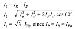
Similarly, the remaining two line currents, I2 and I3, are also equal to √3 times the phase currents; i.e. IL = √3 IPh.
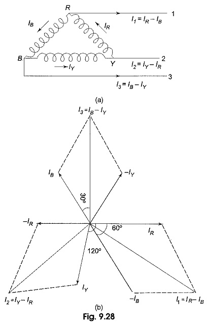
As can be seen from Fig. 9.28(b), all the line currents are equal in magnitude but displaced by 120° from one another; and the line currents are 30° behind the respective phase currents.
Power in the Delta-Connected System:
Obviously the total power in the 3 Phase Delta Connection is the sum of the powers in the three phases. Since the load is balanced, the power consumed in each phase is the same. Total power is equal to three times the power in each phase.
![]()
where Φ is the phase angle between phase voltage and phase current.
![]()
In terms of line quantities
![]()
Since
![]()
for a balanced system, whether star or delta, the expression for the total power is the same.
N-Phase Mesh System:
Figure 9.30(a) shows part of an n-phase balanced mesh system. Its vector diagram is shown in Fig. 9.30(b).
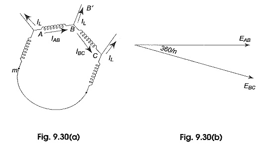
Let the current in line BB’ be IL.. This is same in all the remaining lines of the n-phase system. IAB, IBC are the phase currents in AB and BC phases respectively. The vector addition of the line current is shown in Fig. 9.30(c). It is evident from the Fig. 9.30(b) that the line and phase voltages are equal.
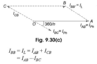
Consider the parallelogram OABC.
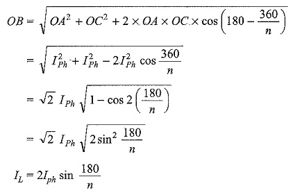
The above equation is a general equation for the line current n a balanced n-phase mesh system.