Current Sensing of Electrical Drives:
Current Sensing of Electrical Drives is required for the implementation of current limit control, inner current control loop of closed-loop speed control, closed-loop torque control of a dc drive, for sensing fault conditions, and for sensing speed in dc drives by back emf sensing method. In order to avoid interaction between control circuit, carrying low voltage and current, and power circuit involving high voltage and current and sometimes harmonics and voltage spikes, isolation must be provided between the two circuits.
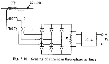
Current in three-phase ac circuits can be sensed using the circuit shown in Fig. 3.10. Current transformers (CT) are used to provide isolation. The current transformer output is rectified, applied across resistor R and then filtered. Voltage drop V0 is proportional to the current in ac lines. When used in variable frequency inverters care should be taken to avoid saturation at low frequencies. Major limitation of this method is that it cannot sense the phase of currents.
It case of fully-controlled rectifiers, dc link current is proportional to ac line currents. Therefore, in dc and ac drives fed from fully-controlled rectifier, dc link current can be sensed indirectly by sensing ac line currents of rectifier by the method of Fig. 3.10.
A number of methods are available for sensing dc current. Two commonly used methods are:
(i) This involves the use of a current sensor employing Hall-effect. It has the ability to sense current direction and is commercially available for a wide range of currents (few amperes to several hundred amperes) with a typical accuracy of 1% up to 400 Hz:
(ii) It involves the use of a non-inductive resistance shunt in conjunction with an isolation amplifier which has an arrangement for amplification and isolation between power and control circuits.
Main limitation of shunt is that it provides only a small output voltage of the order of 7.5 to 75 mV at the rated current. Use of shunts of higher resistance results in the increased power dissipation and drift of resistance with temperature. In current control loop of a variable speed drive, accurate sensing of current is not necessary, and therefore, the drop across a suitable winding, e.g. interpole winding in a dc machine, is often used for Current Sensing of Electrical Drives.
Isolation amplifier may consist of any one of the following circuits: Voltage drop across the shunt is filtered, amplified, modulated and then applied to primary of an isolation transformer. Output of the transformer is demodulated by a phase sensitive demodulator, filtered, buffered and applied to output terminals. This method allows the sensing of current direction. In alternative scheme, shunt voltage drop is filtered, amplified and then processed through an opto-isolator Opto-isolator output is buffered and then brought to the output terminals. Since opto-isolator gain is temperature dependent and non-linear, two identical opto-isolator are employed in a feedback loop to compensate for these non-linearities.