Current Limit Control of Drives:
Current Limit Control of Drives scheme of Fig. 3.3 is employed to limit the converter and motor current below a safe limit during transient operations. It has a current feedback loop with a threshold logic circuit. As long as the current is within a set maximum value, feedback loop does not affect operation of the drive.
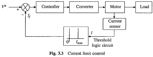
During a transient operation in Current Limit Control of Drives, if current exceeds the set maximum value, feedback loop becomes active and current is forced below the set maximum value, which causes the feedback loop to become inactive again. If the current exceeds set maximum value again, it is again brought below it by the action of feedback loop. Thus the current fluctuates around a set maximum limit during the transient operation until the drive condition is such that the current does not have a tendency to cross the set maximum value, e.g. during starting, current will fluctuate around the set maximum value. When close to the steady-state operation point, current will not have tendency to cross the maximum value, consequently, feedback loop will have no effect on the drive operation.
Speed Sensing:
Sensing of speed is required for implementation of closed-loop speed control schemes. Speed is usually sensed using tachometers coupled to the motor shaft. A tachometer is an ac or dc generator with a high order of linearity between its speed and output voltage. A dc tachometer is built with a permanent magnetic field and sometimes with silver brushes to reduce contact drop between the brush and commutator. Typical voltage outputs are 10 V per 1000 rpm.
The tachometer output voltage consists of a ripple whose frequency depends on its speed. At low speeds, adequate filtering can only be done by a filter with a large enough time constant to affect the dynamics of the drive. Special large diameter tachometers with a large number of commutator segments are sometimes built to overcome this problem. Tachometers are available to measure speed with an accuracy of ± 0.1%. Tachometer should be coupled to the motor with a torsionally stiff coupling so that natural frequency of the system consisting of rotor of the motor and tachometer lies well beyond the bandwidth of the speed control loop. When very high speed accuracies are required, as in computer peripherals and paper mills etc., digital tachometers are used.
A digital tachometer employs a shaft encoder which gives a frequency proportional to the motor speed. Encoder consists of a transparent plastic or aluminium disc mechanically coupled to the motor shaft. Transparent plastic disk is alternately painted black on its peripheri to provide alternately transparent and non-transparent parts. In an aluminium disc, a number of holes or slots are uniformly made around its peripheri. An opto-coupler unit, consisting of a light source and a light sensor, is so mounted that the disc will run in between light source and the sensor.
Sensor senses the light source whenever a transparent part/slot/hole crosses opto-coupler and a voltage pulse is produced. Frequency of the pulse train is proportional to the speed of shaft. Pulses are counted over a specific period to obtain a number proportional to speed.
In dc drives, speed can be sensed without a tachometer when field current is held constant. Use is made of the fact that the beak emf is directly proportional to speed when flux is held constant. The back emf is measured by deducting from motor terminal voltage a signal equal to its armature resistance drop. Accuracy of measurement is affected by difficulty in sensing armature current accurately due to the presence of ripple, variation of flux due to field supply disturbance and variation of temperatures of field and armature windings. Method is inexpensive and provides speed measurement with an accuracy of ± 2% of base speed.