Leading Power Factor Load
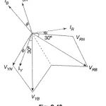
Leading Power Factor Load: Suppose the load in Fig. 9.46(a) is capacitive, the wattmeter connected in the leading phase would read less value. In that case, WR will be the…
Continue Reading
Leading Power Factor Load
Leading Power Factor Load: Suppose the load in Fig. 9.46(a) is capacitive, the wattmeter connected in the leading phase would read less value. In that case, WR will be the…
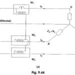
Power in Three Phase Circuits: Measurement of power by a wattmeter in a single phase circuit can be extended to measure Power in Three Phase Circuits. From earlier Section, it…
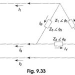
Unbalanced Three Phase Circuit Analysis: Types of Unbalanced Loads - An unbalance exists in a circuit when the impedances in one or more phases differ from the impedances of the…
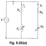
Locus Diagram of Parallel RLC Circuit: (a) Variable XL - Locus plots are drawn for parallel branches containing RLC elements in a similar way as for series circuits. Here we…
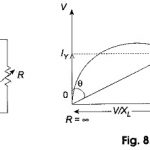
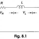
Locus Diagram of RL Series Circuit: To discuss the basis of representing a Locus Diagram of RL Series Circuit by means of a circle diagram consider the circuit shown in…
Series Resonance Circuit: Series Resonance Circuit - In many electrical circuits, resonance is a very important phenomenon. The study of resonance is very useful, particularly in the area of communications.…
Two Port Network Articles: Terminal Pairs or Ports: A pair of terminals at which an electrical signal may enter or leave a network is called a port. The terminals or…
Network Topology in Network Analysis Articles: Indefinite Admittance Matrix: Consider Indefinite Admittance Matrix of a linear network with n terminals as shown in the Fig. 5.26. Let us consider a…