Key Diagram of Substation
Key Diagram of Substation 66/11KV: Fig. 25.10 shows the key diagram of a typical 66/11 kV sub-station. The Key Diagram of Substation can be explained as under: 1. There are…
Continue Reading
Key Diagram of Substation
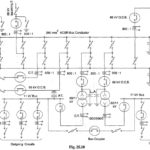
Key Diagram of Substation 66/11KV: Fig. 25.10 shows the key diagram of a typical 66/11 kV sub-station. The Key Diagram of Substation can be explained as under: 1. There are…
Substation: The assembly of apparatus used to change some characteristic (e.g. voltage, ac. to dc., frequency, p.f. etc.) of electric supply is called a Substation. Sub-stations are important part of…
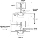
Induction Type Directional Overcurrent Relay: The directional power relay is unsuitable for use as a directional protective relay under short-circuit conditions. When a short-circuit occurs, the system voltage falls to…
Circuit Breaker Ratings: A Circuit Breaker Ratings may be called upon to operate under all conditions. However, major duties are imposed on the Circuit Breaker Ratings when there is a…
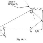
Voltage Control by Synchronous Condenser: The voltage at the receiving end of a transmission line can be controlled by installing specially designed synchronous motors called synchronous condensers at the receiving…
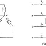
Three Phase Unbalanced Load: The 3-phase loads that have the same impedance and power factor in each phase are called balanced loads. The problems on balanced loads can be solved…
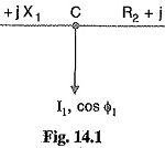
AC Distribution Calculations: AC Distribution Calculations differ from those of d.c. distribution in the following respects : In case of d.c. system, the voltage drop is due to resistance alone.…
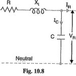
Medium Transmission Line Voltage: In short transmission line calculations; the effects attic line capacitance are neglected because such lines have smaller lengths and transmit power at relatively low voltages (<20…