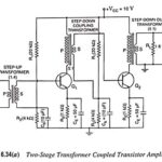
Transformer Coupled Transistor Amplifier – Working Principle
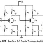
Transformer Coupled Transistor Amplifier - Working Principle: The main cause for low voltage and power gains of an R-C coupled amplifier is that the effective load (Rac) of each stage…
What is Low Frequency Compensation? The coupling or blocking capacitor tilts the amplifier response for step input. In Fig. 16.28, if a high value of resistance Rd is added in…
RC Coupled Transistor Amplifier - Operations, Derivation and Applications: A two-stage RC Coupled Transistor Amplifier using N-P-N transistors in CE configuration is shown in Fig. 16.12. The two transistors used are…
Step Response of an Amplifier: An alternative criterion of amplifier fidelity is the response of the amplifier to a particular input waveform. Of all possible available waveforms, the most generally…
Frequency Response of RC Coupled Amplifier: The curve drawn between the voltage gain and signal frequency of an amplifier is known as the frequency response. The performance of an frequency…
What is Multistage Amplifier? - Types, Block Diagram and Analysis Amplifiers that produce voltage, current, and/or power gain through the use of two or more stages are called multistage amplifiers.…
Miller Effect in Amplifier Frequency Response: According to this effect, when viewed from the input base terminal of the CE-connected transistor the capacitance Ccb appears as (1 - Av)Ccb i.e., it is…
Effect of Internal Transistor Capacitance: As we know already that at high frequencies, the coupling and bypass capacitors act as short circuit due to their low reactance and hence the…