Bias Circuit Design
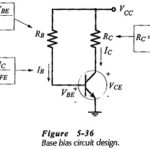
Bias Circuit Design: Bias Circuit Design can be amazingly simple. Usually, it is just a matter of determining the required voltage across each resistor and the appropriate current levels. Then,…
Comparison of Different Biasing Circuits: The Comparison of Different Biasing Circuits of the three basic bias circuits, it must be recalled that transistor manufacturers specify maximum and minimum hFEÂ values for…
Collector to Base Bias Circuit: The Collector to Base Bias Circuit shown in Fig. 5-17(a) has the base resistor (RB) connected between the transistor collector and base terminals. As will…
Tunnel Diode Equivalent Circuit: The Tunnel Diode Equivalent Circuit, when biased in the negative-resistance region, is shown in Figure 12-18. At all except the highest frequencies, the series resistance and…
Power System Stability Articles: What is Power System Stability?: The stability of an interconnected power system is its ability to return to normal or stable operation after having been subjected…
Linear Integrated Circuits Articles: Linear integrated circuits and applications | Op Amp Basics: Linear integrated circuits and applications – The term IC means integrated circuit where all the components are…
Deltatron Circuit or Cascaded Modular Voltage Multipliers: A combination of Cockcroft-Walton type voltage multiplier with cascaded transformer d.c. rectifier is developed recently for very high voltages but limited output currents having…
Stability from Log Magnitude Angle Diagram: Yet another way of portraying the frequency response is to draw a curve showing the Log Magnitude Angle Diagram in decibels on the Y-axis…