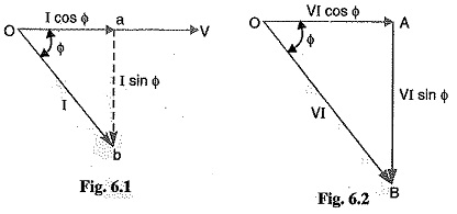
Power Triangle:
The analysis of power factor can also be made in terms of power drawn by the a.c. circuit. If each side of the current triangle oab of Fig. 6.1 is multiplied by voltage V, then we get the power triangle OAB shown in Fig. 6.2 where
The following points may be noted form the power triangle :
The apparent power in an a.c. circuit has two components viz., active and reactive power at right angles to each other.
Thus the power factor of a circuit may also be defined as the ratio of active power to the apparent power. This is a perfectly general definition and can be applied to all cases, whatever be the waveform.
The lagging reactive power is responsible for the low power factor. It is clear from the power triangle that smaller the reactive power component, the higher is the power factor of the circuit.
For leading currents, the power triangle becomes reversed. This fact provides a key to the power factor improvement. If a device taking leading reactive power (e.g. capacitor) is connected in parallel with the load, then the lagging reactive power of the load will be partly neutralised, thus improving the power factor of the load.
The power factor of a circuit can be defined in one of the following three ways :
The reactive power is neither consumed in the circuit nor it does any useful work. It merely flows back and forth in both directions in the circuit. A wattmeter does not measure reactive power.
Illusfration. Let us illustrate the power relations in an a.c. circuit with an example. Suppose a circuit draws a current of 10 A at a voltage of 200 V and its pl. is 0.8 lagging. Then,
The circuit receives an apparent power of 2000 VA and is able to convert only 1600 watts into active power. The reactive power is 1200 VAR and does no useful work. It merely flows into and out of the circuit periodically. In fact, reactive power is a liability on the source because the source has to supply the additional current (i.e., I sin Φ).


