Microprocessor 8086 Pin Configuration Articles:
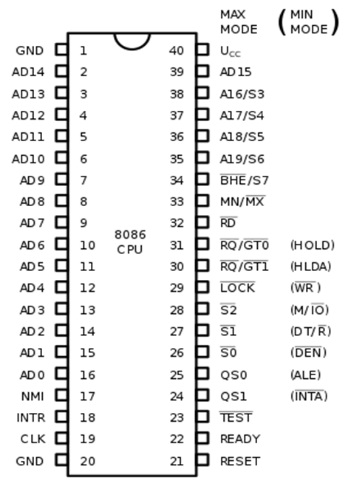
8086 Microprocessor Pin Diagram and 8088 Pin Diagram : In order to implement many situations in the microcomputer system the 8086 Microprocessor Pin Diagram and 8088 Pin Diagram has been designed to work in two operating modes : Minimum Mode Configuration of 8086 Maximum Mode Configuration of 8086 The Minimum Mode Configuration of 8086 is used for a small systems with a single processor and …
Address Decoding Techniques in 8086 Microprocessor : The Different types of Address Decoding Techniques in 8086 Microprocessor are, Absolute decoding Linear decoding Block decoding 1. Absolute Decoding : In absolute decoding technique the memory chip is selected only for the specified logic level on the address lines; no other logic levels can select the chip. Fig 10.12 shows the memory interface. with absolute decoding. Two 8K EPROMs …
Maximum Mode Configuration of 8086 : A processor is in the Maximum Mode Configuration of 8086 when its MN/MX pin is grounded. The maximum mode defines pins 24 to 31 as follows: Pin Definitions (24 to 31) in Maximum Mode: 1.QS1, QS0 (output) : These two output signals reflect the status of the instruction queue. This status indicates the activity in the queue during …
Memory Addressing Modes of 8086 : Most of the memory ICs are byte oriented i.e. each memory location can store only one byte of data. The 8086 is a 16-bit microprocessor, it can transfer 16-bit data. So in addition to byte, word (16-bit) has to be stored in the memory. This is stored by using two consecutive memory locations, one for least …
Minimum Mode Configuration of 8086 : Pin definitions from 24 to 31 are different for minimum mode and maximum mode. By using these pins the 8086 itself generates all bus control signals in the Minimum Mode Configuration of 8086. These signals are : Pin Definitions (24 to 31) in Minimum Mode: INTA (Interrupt Acknowledge) Output : This indicates recognition of an interrupt request. It …