Effects of Harmonics:
The relationship between line and phase quantities for wye and delta connections as derived earlier are strictly valid only if the source voltage is purely sinusoidal. Such a waveform is an ideal one. Modern alternations are designed to give a terminal voltage which is almost sinusoidal. But it is nearly impossible to realize an ideal waveform in practice. All sinusoidally varying alternating wave forms deviate to a greater or lesser degree, from an ideal sinusoidal shape. Due to non-uniform distribution of the field flux and armature reaction in a. c. machines, the current and voltage waves may get distorted. Such wave forms are referred to as non-sinusoidal or complex wave forms. In modem machines this distortion is relatively small. All non-sinusoidal waves can be broken up into a series of sinusoidal waves whose frequencies are integral multiples of the frequency of the fundamental wave. The sinusoidal components of a complex wave are called harmonics. It is therefore necessary to consider the effect of certain Effects of Harmonics on currents and voltages in the phase of three-phase wye and delta systems in effecting the line and phase quantities.
The fundamental wave is called the basic wave or first harmonic. The second harmonic has a frequency of twice the fundamental, the third harmonic frequency is three times the fundamental frequency and so on. Each harmonic is a pure sinusoid. Waves having 2f, 4f, 6f etc. are called even harmonics and those having frequencies 3f 5f, 7f, etc. are called odd harmonics. Since the negative half of the wave is a reproduction of the positive half, the even harmonics are absent. Therefore, a complex wave can be represented as a sum of fundamental and odd harmonics.
Harmonic Effect in Wye:
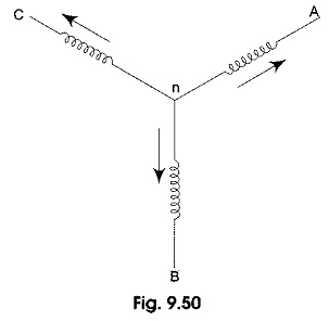
Let us consider a wye connected generator winding, whose arrangement is shown diagrammatically in Fig. 9.50. The voltage induced in phase a of the three-phase symmetrical system, including odd harmonics is given by
![]()
Where Em1, Em3, Em5, etc. are the peak values of the fundamental and other Effects of Harmonics and θ1, θ3, θ5, etc. are phase angles. Assuming abc phase sequence. The voltage in phase b will be
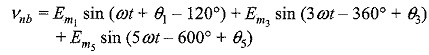
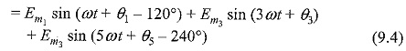
The voltage in phase c will be
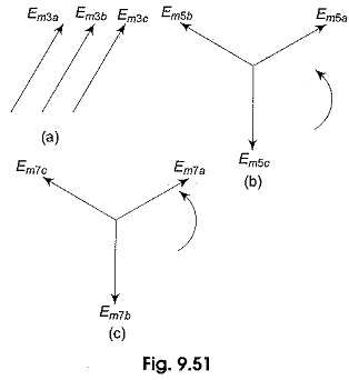
Equations 9.3, 9.4, and 9.5 show that all third harmonics are in time phase with each other in all the three phases as shown in Fig. 9.51(a). The same applies to the, ninth, fifteenth, twenty first … harmonics, i.e. all odd multiples of 3. Other than odd multiples of 3, the fifth, seventh, eleventh.., and all other harmonics are displaced 120° in time phase mutually with either the same phase sequence or opposite phase sequence compared with that of the fundamentals. Fifth harmonics and seventh harmonic sequences are shown in Figs. 9.5(c) and 9 5(d) respectively.
Summarizing the above facts, the fundamental and all those harmonics obtained by adding a multiple of 6, i.e. 1, 7, 13, 19… etc. will have the same sequence. Similarly, the fifths and all Effects of Harmonics obtained by adding a multiple of 6, i.e. 5, 11, 17, 23 … etc. will have sequence opposite to that of the fundamental.
Voltage Relations:
The Voltage between lines ab in the wye connected winding in Fig. 9.50 may be written as
![]()
Adding of each harmonic separately is shown in Fig. 9.52.
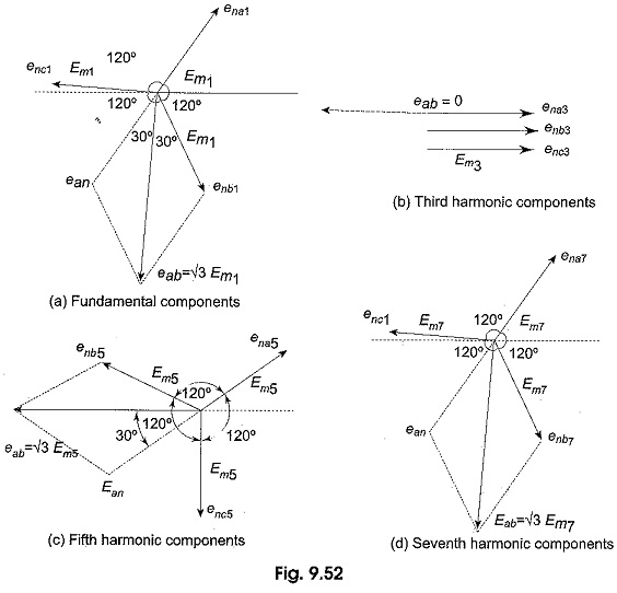
It is seen from the vector diagrams of Fig. 9.52 that there is no third harmonic component in the line voltage. Hence, the rms value of the line voltage is given by
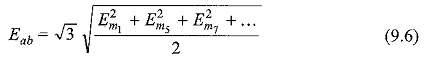
From equation (1) the rms value of the phase voltage is
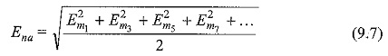
It is seen from the above equations that in a wye connected system, the line voltage is not equal to √3 times the phase voltage if harmonics are present. This is true only when the third harmonics are absent.
Current Relations:
Similar to the complex voltage wave the instantaneous value of the complex current wave can be written
![]()
where Im1, Im3, Im5, etc. are the peak values of fundamental and other harmonics; (Φ1 – Φ1) is the phase difference between fundamental component of the harmonic voltage and current and (Φ3 – Φ3) is the phase difference between 3rd harmonics and so on. Applying KCL for the three phase wye connected winding in Fig. 9.50.
![]()
The equations for ina, inb and inc can be obtained by replacing currents in the place of voltages in equations 9.3, 9.4 and 9.5 under balanced conditions the sum of the three currents is equal to zero, only when they have equal magnitudes and displaced by 120° apart in time phase in the three phases. All harmonics fulfill the above condition except the third harmonics and their odd multiples as they are in the same phase as shown in Fig. 9.51(a) or 9.52(b). Hence, the resultant of ina + inb + inc consists of the arithmetic sum of the third harmonics in the three phases. Hence, there must be a neutral wire or fourth wire to provide a return path for the third harmonic. We can summarize the above facts as follows. In a balanced three-wire wye connection, all harmonics are present except third and its odd multiples. In a four-wire wye connection, i.e. with a neutral wire, all harmonics will exist.
Effects of Harmonics in Delta:
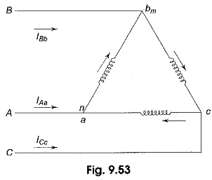
Let the three windings of the generator be delta-connected as shown in Fig. 9.53. Let υna, υnb and υnc be the phase emfs and υna, υnb and υnc be the terminal voltages of the three phases a, b and c respectively. According to KVL the algebraic sum of the three terminal voltages in the closed loop is given by
![]()
There will be a circulating current in the closed loop due to the resultant third harmonic and their multiple induced emfs. This resultant emf is dropped in the closed loop impedance. Hence, the third harmonic voltage does not appear across the terminals of the delta. Hence, the terminal voltages in delta connection υca, υab and υbc are given by equations 1, 2 and 3 respectively without third harmonic terms.
Current Relations:
The three phase windings in Fig. 9.53, carry all the harmonics internally and are given by
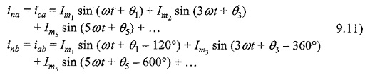
Equations 9.11, 9.12 and 9.13 represent the phase currents in the delta connection. The line currents IAa IBb and ICc can be obtained by applying KCL at the three junctions of the delta in Fig. 9.53. The current vector diagrams are similar to the voltage vector diagrams shown in Fig. 9.52 except that the voltages are to be replaced with currents. The line currents can be obtained in terms of phase currents by applying KCL at three junctions as follows
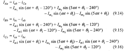
Equations 9.14, 9.15 and 9.16 indicate that no third harmonic currents can exist in the line currents of a delta connection.
The rms value of the line current from the above equation is
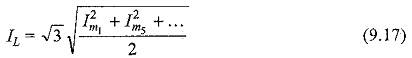
The rms value of the phase current from Equations 9.11, 9.12 and 9.13 is given by
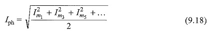
It is seen from Equations 9.17 and 9.18, that in a delta-connected system the line current is not equal to √3 times the phase current. It is only true when there are no third harmonic currents in the system.