Signal Generators in Electronic Devices

Crystal Equivalent Circuit

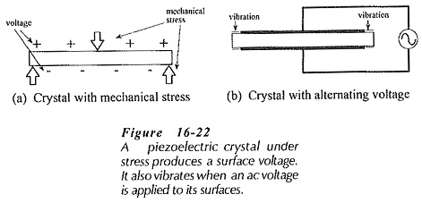
Crystal Equivalent Circuit: Crystal Equivalent Circuit – The output frequency of oscillator circuits is normally not as stable as required for a great many applications. The component values all have tolerances, so that the actual oscillating frequency may easily be 10% higher or lower than the desired frequency. However, by making a capacitor or resistor …

Crystal Equivalent Circuit Read More »

Oscillator Amplitude Stabilization Circuit

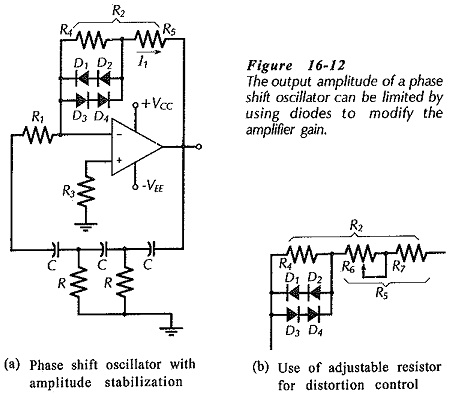
Oscillator Amplitude Stabilization Circuit: Output Amplitude – For all of the Oscillator Amplitude Stabilization Circuit discussed, the output voltage amplitude is determined by the amplifier maximum output swing. The output waveform may also be distorted by the amplifier output saturation limitations. To minimize distortion and reduce the output voltage to an acceptable level, amplitude stabilization …

Oscillator Amplitude Stabilization Circuit Read More »

Hartley Oscillators using Op-Amp

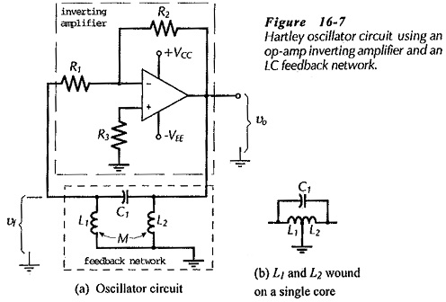
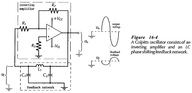
Hartley Oscillators using Op-Amp: Hartley Oscillators using Op-Amp circuit is similar to the Colpitts oscillator, except that the feedback network consists of two inductors and a capacitor instead of two capacitors and an inductor. Figure 16-7(a) shows the Hartley Oscillators using Op-Amp circuit, and Fig. 16-7(b) illustrates the fact that L1 and L2 may be …

Hartley Oscillators using Op-Amp Read More »

RC Phase Shift Oscillator Circuit Diagram

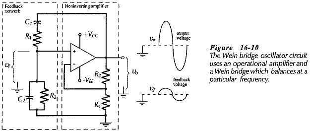
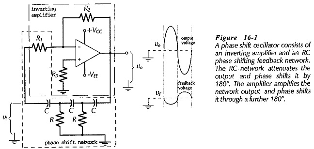
RC Phase Shift Oscillator Circuit Diagram: Figure 16-1 shows the RC Phase Shift Oscillator Circuit Diagram, which consists of an inverting amplifier and an RC phase-shifting network. The amplifier phase-shifts its input by -180°, and the RC phase-lead network phase-shifts the amplifier output by a +180°, giving a total loop phase shift of zero. The …

RC Phase Shift Oscillator Circuit Diagram Read More »

Scroll to Top