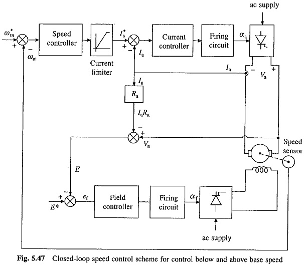
Closed Loop Speed Control of DC Motor
Closed Loop Speed Control of DC Motor: Closed Loop Speed Control of DC Motor - The converters (rectifiers and choppers) are built using semiconductor devices, which have very low thermal capacity. Consequently their transient and…
Comments Off on Closed Loop Speed Control of DC Motor
January 12, 2019