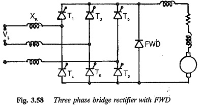
Bridge Rectifier Circuit Diagram with freewheeling diode
Bridge Rectifier Circuit Diagram with freewheeling diode: A 6 pulse Bridge Rectifier Circuit Diagram with freewheeling diode across the load terminals is shown in Fig. 3.58. As has already been explained, the diode participates in…
Comments Off on Bridge Rectifier Circuit Diagram with freewheeling diode
February 1, 2018