Coupled Circuits

Parallel Magnetic Circuit

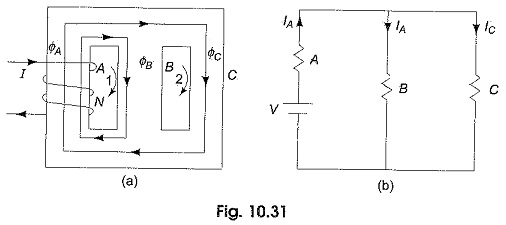
Parallel Magnetic Circuit: We have seen that a series magnetic circuit carries the same flux and the total mmf required to produce a given quantity of flux is the sum of the mmf’ s for the separate parts. In a Parallel Magnetic Circuit, different parts of the circuit are in parallel. For such circuits the […]

Parallel Magnetic Circuit Read More »

Magnetic Leakage and Fringing

Magnetic Leakage and Fringing: Magnetic Leakage and Fringing – Figure 10.28 shows a magnetized iron ring with a narrow air gap, and the flux which crosses the gap can be regarded as useful flux. Some of the total flux produced by the ring does not cross the air gap, but instead takes a shorter route

Magnetic Leakage and Fringing Read More »

Difference Between Electric Circuit and Magnetic Circuit

Difference Between Electric Circuit and Magnetic Circuit: A Difference Between Electric Circuit and Magnetic Circuit are shown in Figs. 10.27(a) and (b) respectively. Figure 10.27(a) represents an electric circuit with three resistances connected in series, the dc source E drives the current I through all the three resistances whose voltage drops are V1,V2 and V3. Hence,

Difference Between Electric Circuit and Magnetic Circuit Read More »

Series Magnetic Circuit

Series Magnetic Circuit: A series magnetic circuit is analogous to a series electric circuit. Kirchhoff s laws are applicable to magnetic circuits also. Consider a ring specimen having a magnetic path of l meters, area of cross-section (A)m2 with a mean radius of R meters having a coil of N turns carrying I amperes wound

Series Magnetic Circuit Read More »

Magnetic Circuit Analysis

Magnetic Circuit Analysis: Magnetic Circuit Analysis – The presence of charges in space or in a medium creates an electric field, similarly the flow of current in a conductor sets up a magnetic field. Electric field is represented by electric flux lines, magnetic flux lines are used to describe the magnetic field. The path of

Magnetic Circuit Analysis Read More »

Doubled Tuned Coupled Circuits

Doubled Tuned Coupled Circuits: Figure 10.24 shows a Doubled Tuned Coupled Circuits involving two series resonant circuits. For the circuit shown in the figure, a special case where the primary and secondary resonate at the same frequency ωr, is considered here, i.e. The two mesh equations for the circuit are From which or where A

Doubled Tuned Coupled Circuits Read More »

Single Tuned Circuit

Single Tuned Circuit: Consider the Single Tuned Circuit in Fig. 10.21. A tank circuit (i.e. a parallel resonant circuit) on the secondary side is inductively coupled to coil (1) which is excited by a source, υi. Let Rs be the source resistance and R1,R2 be the resistances of coils, 1 and 2, respectively. Also let L1,L2

Single Tuned Circuit Read More »

Inductively Coupled Circuits

Inductively Coupled Circuits: Inductively coupled multi-mesh circuits can be analysed using Kirchhoff s laws and by loop current methods. Consider Fig. 10.17, where three coils are inductively coupled. For such a system of inductors we can define a inductance matrix L as where L11, L22 and L33 are self inductances of the coupled circuits, and L12 =

Inductively Coupled Circuits Read More »

Scroll to Top