Voltage and Current in Series Resonant Circuit
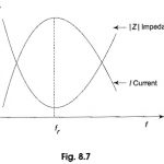
Voltage and Current in Series Resonant Circuit: The variation of impedance and current with frequency of Voltage and Current in Series Resonant Circuit is shown in Fig. 8.7. At resonant…
Impedance and Phase Angle of Series Resonant Circuit: The impedance of a Series Resonant Circuit is The variation of XC and XL with frequency is shown in Fig. 8.4. At…
Coupled Circuit Articles: Coupled Circuits Definition: Two circuits are said to be ‘coupled’ when energy transfer takes place from one circuit to the other when one of the circuits is…
HVDC Circuit Breakers - Construction and Working Principle: Light duty dc circuit breakers have been in use since long. However, there is lack of suitable circuit breakers for HVDC systems.…
Large Signal Tuned Amplifier - Operation and its Equivalent Circuit: Tuned amplifier circuits are for class A operation and their use is limited to applications in which RF signal has…
Double Tuned Amplifier - Circuit Diagram and Operation: The problem of potential instability with a single tuned amplifier is overcome in a double tuned amplifier which consists of inductively coupled…
Crystal Oscillators - Circuit, Working, Advantages and Disadvantages: In crystal oscillators, the usual electrical resonant circuit is replaced by a mechanically vibrating crystal. The crystal (usually quartz) has a high…
Clapp Oscillator - Circuit Diagram and Operation: The Clapp oscillator shown in Fig. 21.15 is a refinement of the Colpitt's oscillator. The single inductor found in the Colpitt's oscillator is…