Arithmetic Instructions in 8051:
The Arithmetic Instructions in 8051 of Basic Assembly Language Programming are
ADD, ADDC, SUBB and DA
The ADD instruction adds a byte variable with the accumulator, leaving the result in the accumulator: The carry flag is set if there is an overflow from bit 7 and cleared otherwise. The AC flag is set to the carry-out from bit 3 for use by the DA instruction described later. ADDC adds the previous contents of the carry flag with the two byte variables, but otherwise is the same as ADD:
The SUBB (subtract with borrow ) instruction subtracts the byte variable indicated and . the contents of the carry flag together from the accumulator, and puts the result back in the accumulator. The carry flag serves as a “Borrow Required” flag during subtraction operations when a greater value is subtracted from a lesser value (as in subtracting 5 from 1) requiring a borrow into the highest order bit, the carry flag is set; otherwise it is cleared.
When performing signed binary arithmetic; certain combinations of input variables can produce results which seem to violate the Laws of Mathematics. For example, adding 7FH (127) to itself produces a sum of – 2. In “normal” arithmetic, two positive values can not have a negative sum. Similarly, it is normally impossible to subtract a positive value from a negative value and leave a positive result, but in two’s complement there are instances where this too may happen. Fundamentally, such conditions occur when the magnitude of the resulting value is too great to “fit” into the seven bits allowed for it. These conditions are referred as overflow. The MCS 51 indicates such errors with the OV flag. The ADDC/ SUB instructions add/ subtract a byte variable from the accumulator with carry/borrow.
Decimal addition is possible by using the DA instruction in conjunction with ADD and/or ADDC. The eight-bit binary value in the accumulator resulting from an earlier addition of two variables (each a packed BCD digit-pair) is adjusted to form two BCD digits of four bits each. If the contents of accumulator bits 3-0 are greater than nine or if the AC flag had been set, six is added to accumulator producing the proper BCD digiLin the low-order nibble. (This addition might itself set – but would not clear- the carry flag.) If the carry flag is set, or if the four high-order bits now exceed nine these bits are incremented by six. The carry flag is left set if originally set or if either addition of six produces a carry out of the highest-order bit, indicating the sum of the original two BCD variables is greater than or equal to decimal 100.
Multiplication and Division:
The instruction “MUL AB” multiplies the unsigned eight-bit integer values held in the accumulator and B-register. The low-order byte of the sixteen-bit product is left in the accumulator, the higher-order byte in B. If the high-order eight-bits of the product are all zero, the overflow flag is cleared; otherwise it is set. The programmer can check OV to determine when the B register is non-zero and must be processed.
“DIV AB” divides the unsigned eight-bit integer in the accumulator by the unsigned eight-bit integer in the B-register. The integer part of the quotient is returned in the accumulator, the remainder in the B register. If the B-register originally contains OOH then the overflow flag will be set to indicate a division error, and the values returned will be undefined. Otherwise OV is cleared.
The divide instruction is also useful for purposes such as radix conversion or separating bit fields of the accumulator. A short subroutine can convert an eight-bit unsigned binary integer in the accumulator (between 0 and 255) to a three-digit (two byte) BCD representation. The hundred’s digit is returned in one register (HUND) and the ten’s and one’s digits returned as packed BCD in another (TENONE).
Logical Byte Operations:
ANL, ORL, XRL
The instructions ANL, ORL, and XRL perform the logical functions AND, OR; and/or Exclusive-OR on the two byte variables indicated, leaving the results in the first. No flags are affected.
These operations may use all the same addressing modes as the arithmetics (ADD etc.) but unlike the arithmetics, they are not restricted to operate on the accumulator. Directly addressed bytes may be used as the destination with either the accumulator or a constant as the source. These instructions are useful for clearing (ANL), setting (ORL), or complementing (XRL) one or more bits in a RAM, output ports, or control registers.
Program Control:
Jumps, Calls, Returns
The Arithmetic Instructions in 8051 has three forms of jump instruction. Each causes the program to unconditionally jump to some other address. They differ in how the machine code represents the destination address.
LJMP (Long Jump) encodes a sixteen-bit address in the second and third instruction bytes (Fig. 12.31) ; the destination may be anywhere in the 64 Kilobyte program memory address space.-
The two byte AJMP (Absolute Jump) instruction encodes its destination using address bits 10 through 8 form a three bit field in the opcode and address bits 7 through 0 form the second byte. Address bits 15-12 are unchanged from the (incremented) contents of the PC, so AJMP can only be used when the destination is known to be within the same 2K memory block (otherwise Arithmetic Instructions in 8051 will point out the error).
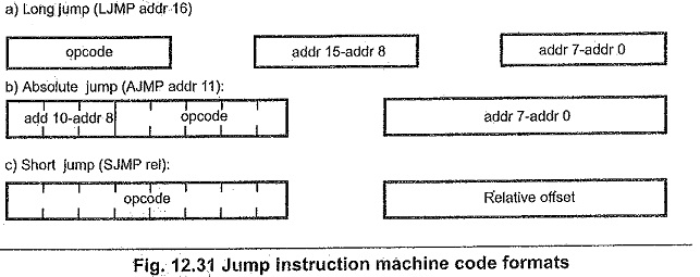
A different two-byte jump instruction is legal with any nearby destination, regardless of memory block boundaries or “pages” SJMP (Short Jump) encodes the destination with a program counter-relative address in the second byte. The CPU calculates the destination at run-time by adding the signed eight-bit displacement value to the incremented PC.
Negative offset values will cause jumps upto 128 bytes backwards; positive values up to 127 bytes forwards. (SJMP with 00H in the machine code offset byte will proceed with the following instruction).
Like SJMP all conditional jump instructions use relative addressing. JZ ( Jump if Zero ) and JNZ (Jump if Not Zero) monitor the state of the accumulator as implied by their names, while JC (Jump on Carry ) and INC (Jump on No Carry) test whether or not the carry flag is set. All four are two-byte instructions. JB (Jump on Bit), JNB (Jump on No Bit) and JBC (Jump on Bit then Clear Bit) can test any status bit or input pin.with a three byte instruction; the second byte specifies which bit to test and the third gives the relative offset value.
There are two subroutine-call instructions. LCALL (Long Call) and ACALL (Absolute Call). Each increments the PC to the first byte of the following instruction, then pushes it onto the stack (low byte first). Saving both bytes increment the stack pointer by two. The subroutine’s starting address is encoded in the same ways as LJMP and AJMP. The generic form of the call operation is the mnemonic CALL, which Arithmetic Instructions in 8051 will translate into LCALL or ACALL as appropriate.
The return instruction RET pops the high and low-order bytes of the program counter successively from the stack, decrementing the stack pointer by two. Program execution continues at the address previously pushed : the first byte of the instruction immediately following the call.
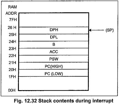
When an interrupt request is recognized by the Arithmetic Instructions in 8051 hardware, two things happen. Program control is automatically “vectored” to one of the interrupt service routine in effect, forcing the CPU to process an LCALL instead of the next instruction. This automatically stores the return address on the stack..
Secondly, the interrupt logic is disabled from accepting any other interrupts from the same or lower priority. After completing the interrupt service routine, executing an RETI (Return from Interrupt) instruction will return execution to the point where the main program was interrupted.
Two groups of instructions combine abyte operation with a conditional jump based on the results.
CJNE (Compare and Jump if Not Eqhal) compares two byte operands and executes a jump if they disagree. The cony flag is set following the rules for subtraction: if the unsigned integer value of the first operand is less than that of the second it is set; otherwise, it is cleared. However, neither operand is modified.
DJNZ (Decrement and Jump if Not Zero) decrements the register or direct address indicated and jumps if the result is not zero, without affecting any flags. This provides a simple means for executing a program loop a given number of times.
Stack Operations:
PUSH, POP
The PUSH instruction increments
the stack pointer by one, then transfers the contents of the single byte variable indicated (direct addressing only) into the internal RAM location addressed by the stack pointer. Conversely, POP copies the contents of the internal RAM location addressed by the stack pointer to the byte variable indicated, then decrements the stack pointer by one. Interrupt service routines must not change any variable or hardware registers modified by the main program, or else the program may Fig. 12.32 Stack contents during interrupt not resume correctly.
PUSH and POP provide an efficient and convenient way to save register states on the stack.
Data Pointer and Lookup Table Instructions:
MOV, INC, MOVC, JMP
The data pointer can be loaded with a 16-bit value using the instruction MOV DPTR. #data 16. The data used is stored in the second and third instruction bytes, high-order byte first. The data pointer is incremented by INC DPTR. A 16-bit increment is performed; an overflow from the low order byte will carry into the high-order byte. Neither instruction affects any flag.
The MOVC (Move Constant) instructions (MOVC A.@ A+DPTR and MOVC. A.@A+PC) read into the accumulator bytes of data from the program memory logical address space. Both use a form of indexed addressing: the former adds the unsigned eight-bit accumulator contents with the sixteen-bit data pointer register, and uses the resulting sum as the address from which the byte is fetched. A sixteen-bit addition is performed : a carry-out from the low-order eight bits may propagate through higher-order bits, but the contents of the DPTR are not altered. The latter form uses the incremented program counter as the base value instead of the DPTR again, neither version affects the. flags.
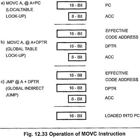
JMP @A+DPTR is an instruction which performs an indirect jump to an address determined during program execution. The instruction adds the eight-bit unsigned accumulator contents with the contents of the sixteen-bit data.pointer, just like MOVC A.@A+DPTR. The resulting sum is loaded into the program counter and is used as the address for subsequent instruction fetch.