Timers and Counters in 8051 Microcontroller:
The Timers and Counters in 8051 Microcontroller has two 16-bit Timer/Counter registers : Timer 0 and Timer 1. The 8052 has these two plus one more : Timer 2. All three can be configured to operate either as timers or event counters.
In the “Timer” mode, the register is incremented after every machine cycle. Thus, one can think of it as counting machine cycles. Since a machine cycle consists of 12 oscillator periods, the count rate is 1/12 of the oscillator frequency.
In the “Counter” mode, the register is incremented in response to, a 1-to-0 transition at its corresponding external input pin, T0, T1 or (in the 8052) T2. In this mode, the external input is sampled during S5P2 of every machine cycle. When the samples show a high in one cycle and a low in the next cycle, the count is. incremented. The new count value appears in the register during S3P1 of the cycle following the one in which the transition was detected. Since it takes 2 machine cycles (24 oscillator periods) to recoginize a 1-to-0 transition, the maximum count rate is 1/24 of the oscillator frequency. There are no restrictions on the duty cycle of the external input signal, but to ensure that a given level is sampled at least once before it changes, it should be held for at least one full machine cycle.
In addition to the “Timer” or “Counter” selection, Timer 0 and Timer 1 have four operating modes from which to select. Timer 2, in the 8052, has three modes of operation : “Capture,” “Auto-Reload” and :Baud rate generator.”
Timer 0 and Timer 1:
These Timers and Counters in 8051 Microcontroller are present in both the 8051 and the 8052. The “Timer” or Counter” mode is selected by control bits C/T in the Special Function Register TMOD. (Fig. 12.15). These two Timers and Counters in 8051 Microcontroller have four operating modes, which are selected by bit-pairs (Ml, M0) in TMOD. Modes 0, 1 and 2 are same for both Timer/Counters. Mode 3 is different. The four operating modes are described as follows :
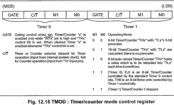
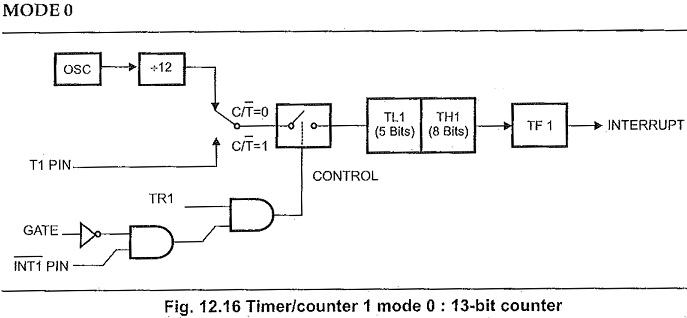

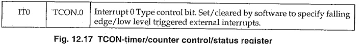
Both Timers and Counters in 8051 Microcontroller in Mode 0 is an 8-bit Counter with a divide-by-32 prescaler. This 13-bit timer is MCS-48 compatible. Fig. 12.16 shows the Mode 0 operation as it applies to Timer 1. In this mode, the Timer register is configured as a 13-bit register. As the count rolls over from all is to all 0s, it sets the Timer interrupt flag TF1. The counted input is enabled to the Timer when TR1 = 1 and either GATE = 0 or INT1 = 1. (Setting GATE =1 allows the Timer to be controlled by external input INT1, to facilitate pulse width measurements.) TR1 is a control bit in the Special Function Register TCON (Fig. 12.17) GATE is in TMOD.
The 13-bit register consists of all 8 bits of TH1 and the lower 5 bits of TL1. The upper 3 bits of TL1 are indeterminate and should be ignored. Setting the run flag (TR1) does not clear the registers.
Mode 0 operation is the same for Timer 0 as for Timer 1. Substitute TR0, TF0 and INT0 for the corresponding Timer 1 signals in Fig. 12.16. There are two different GATE bits, one for Timer 1 (TMOD.7) and one for Timer 0 (TMOD.3).
MODE 1:
Mode 1 is the same as Mode 0, except that the Timer register is being run with all 16 bits.
MODE 2:
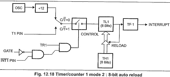
Mode 2 configures the Timer register as an 8-bit Counter (TL1) with automatic reload, as shown in Fig. 12.18. Overflow from TL1 not only sets TF1, but also reloads TL1 with the contents of TH1, which is preset by software. The reload leaves TH1 unchanged. Mode 2 operation is the same for Timer/Counter 0.
MODE 3
Timer 1 in Mode 3 simply holds its count. The effect is the same as setting TR1 = 0. Timer 0 in Mode 3 establishes TL0 and TH0 as two separate counters. The logic for Mode 3 on Timer 0 is shown in Fig. 12.19. TLO uses the Timer 0 control bits : C/T, GATE, TR0, INT0, and TF0. TH0 is locked into a timer mode (counting machine cycles) and takes over the use of TR1 and TF1 from Timer 1. Thus, TH0 now controls the :Timer 1″ interrupt.
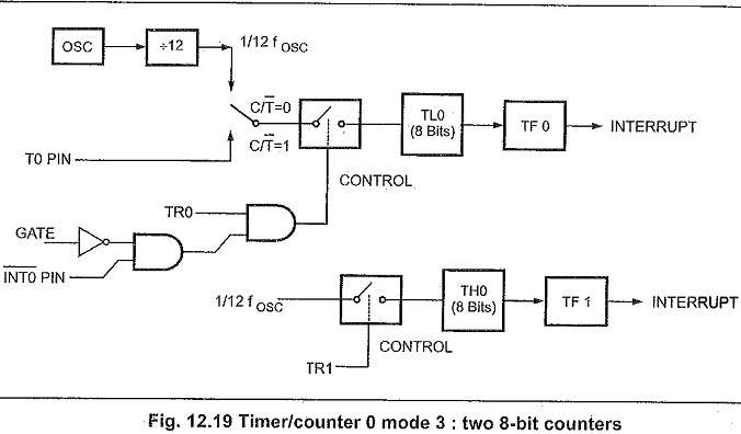
Mode 3 is provided for applications requiring an extra 8-bit timer or counter. With Timer 0 in Mode 3, an 8051 can look like it has three Timers and Counters in 8051 Microcontroller, and an 8052, like it has four. When timer 0 is in Mode 3, Timer 1 can be turned on and off by switching it out of and into its own Mode 3, or can still be used by the serial port as a baud rate generator, or in fact, in any application not requiring an interrupt.
Timer 2 (Only in 8052):
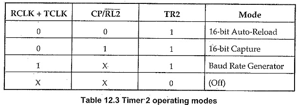
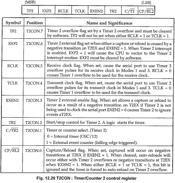
Timer 2 is a 16-bit Timer/Counter which is present only in the 8052. Like Timers 0 and 1, it can operate either as a timer or as an event counter. This is selected by bit C/T2 in the Special Function Register T2CON (Fig. 12.20). It has three operating modes : capture auto-load and baud rate generator, which are selected by bits in T2CON as shown in Table 12.3.
Capture Mode:
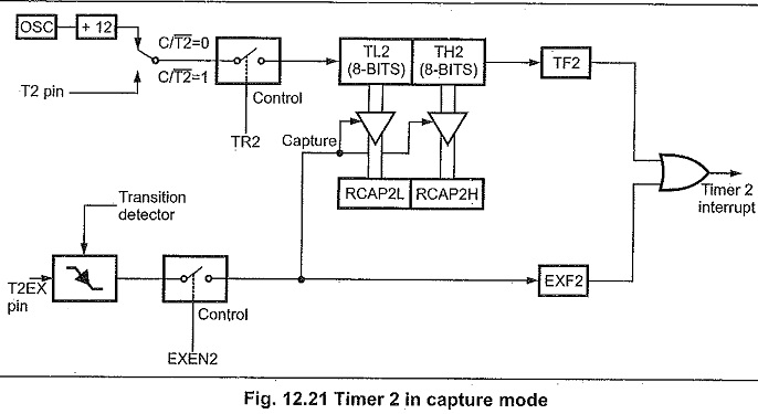
In the Capture Mode there are two options which are selected by bit EXEN2 in T2CON. If EXEN2 = 0, then Timer 2 is a 16-bit Timers and Counters in 8051 Microcontroller which upon overflowing sets bit TF2, the Timer 2 overflow bit, which can be used to generate an interrupt. If EXEN2 = 1, then Timer 2 still does the above, but with the added feature that a 1-to-0 transition at external input T2EX causes the current value in the Timer 2 registers, TL2 and TH2, to be captured into registers RCAP2L and RCAP2H, respectively. (RCAP2L and RCAP2H are new Special Function Register in the 8052). In addition, the transition at T2EX causes bit EXF2 in T2CON to be set, and EXF2, like TF2, can generate an interrupt. The Capture Mode is illustrated in Fig. 12.21.
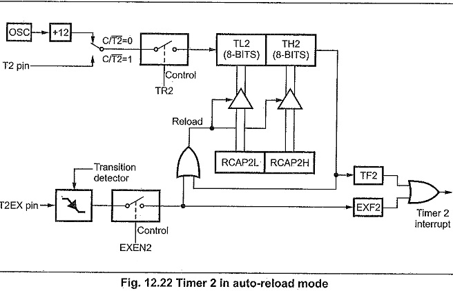
Auto-Reload Mode:
In the auto-reload mode there are again two options, which are selected by bit EXEN2 in T2CON. If EXEN2 = 0, then when Timer 2 rolls over it not only sets TF2 but also causes the Timer 2 registers to be reloaded with the 16-bit value in registers RCAP2L and RCAP2H, which are pfeset by software. If EXEN2 =1, then Timer 2 still does the above, but with the added feature that a 1-to-0 transition at external input T2EX will also trigger the 16-bit reload and set EXF2. The auto-reload mode is illustrated in Fig. 12.22.
Baud Rate Generator Mode:
The baud rate generator mode is selected by RCLK = 1 and /or TCLK = 1. It will be described in conjuction with the serial port.