Torque Slip Characteristics of Induction Motor:
The expression for Torque Slip Characteristics of Induction Motor (T(s)) is easily obtained by finding the Thevenin equivalent of the circuit to the left of ab in Fig. 9.12.
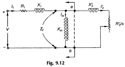

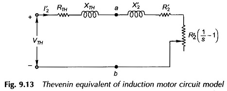
The circuit then reduces to Fig. 9.13 in which it is convenient to take VTH as the reference voltage.
From Fig. 9.13
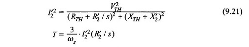
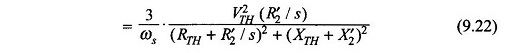
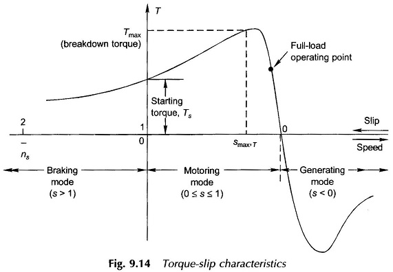
Equation (9.22) is the expression for torque developed as a function of voltage and slip. For a given value of slip, torque is proportional to the square of voltage. The Torque Slip Characteristics of Induction Motor at fixed (rated) voltage is plotted in Fig. 9.14.
Features of the Torque Slip Characteristics of Induction Motor are listed below:
1. Motoring mode: 0 ≤ s ≤ 1
For this range of slip, the load resistance in the circuit model of Fig. 9.13 is positive, i.e. mechanical power is output or torque developed is in the direction in which the rotor rotates. Also:
- Torque is zero at s = 0, as expected by qualitative reasoning.
- The torque has a maximum value, called the breakdown torque, (TBD) at slip smax,T. The motor would decelerate to a halt if it is loaded with more than the breakdown torque.
- At s = 1, i.e. when the rotor is stationary, the torque corresponds to the starting torque, Ts. In a normally designed motor Ts is much less than TBD.
- The normal operating point is located well below TBD. The full-load slip is usually 2.8%.
- The Torque Slip Characteristics of Induction Motor from no-load to somewhat beyond full-load is almost linear.
2. Generating mode: s < 0
Negative slip implies rotor running at super-synchronous speed (n > ns). The load resistance is negative in the circuit model of Fig. 9.13 which means that mechanical power must be put in while electrical power is put out at the machine terminals.
3. Braking mode: s > 1
The motor runs in opposite direction to the rotating field (i.e. n is negative), absorbing mechanical power (braking action) which is dissipated as heat in the rotor copper.
Maximum (Breakdown) Torque:
While maximum torque and the slip at which it occurs can be obtained by differentiating the expression of Eq. (9.22), the condition for maximum torque can be more easily obtained from the maximum power transfer theorem of circuit theory. As we know, the torque is maximum when I′22(R’2/s) is maximum, i.e. maximum power is absorbed by R’2/s in Fig. 9.13. This condition is given as
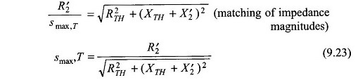
Substituting in Eq. (9.22) and simplifying
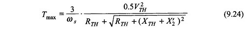
It is immediately observed that the maximum torque is independent of the rotor resistance (R’2) while the slip at which it occurs is directly proportional to it.
The torque slip characteristic of a slip-ring induction motor can be easily modified by adding external resistance as shown in Fig. 9.15a by four such characteristics with a progressively increasing resistance in the rotor circuit. It may be seen that as per Eq. (9.24), the maximum torque remains unchanged while as per Eq. (9.23) the slip at maximum torque proportionally increases as resistance is added to the rotor circuit.
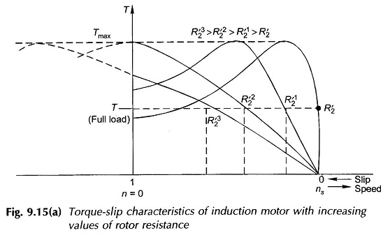
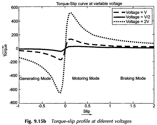
Figure 9.15b indicates the T-s profile at various supply voltages. Speed can also be controlled in this way by changing the stator voltage. It may be noted that the torque developed in an induction motor in proportional to the square of the terminal voltage.
Starting Torque:
Letting s = 1 in Eq. (9.22)
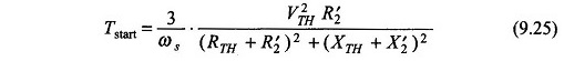
The starting torque increases by adding resistance in the rotor circuit. From Eq. (9.23) the maximum starting torque is achieved for (smax’T=1)
![]()
At the same time the starting current will reduce (see Eq. (9.21)). This indeed is the advantage of the slip-ring induction motor in which a high starting torque is obtained at low starting current.
An Approximation:
Sometimes for getting a feel (rough answer) of the operational characteristic, it is convenient to assume the stator impedance to be negligible which leads to (see Fig. 9.13)
![]()
in the Thevenin equivalent circuit of Fig. 9.13 so that VTH = V. It then follows from Eqs (9.21) to (9.26) that
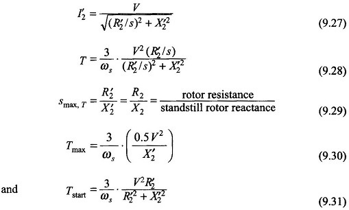
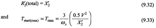
The maximum starting torque is achieved under the condition
Some Approximate Relationships at Low Slip:
Around the rated (full-load) speed, the slip of the induction motor is so small that
![]()
so that X’2 can be altogether neglected in a simplified analysis. Equations (9.27) and (9.28) then simplify to
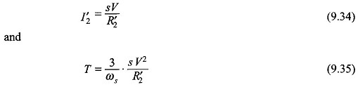
It is immediately observed from Eq. (9.35) that the Torque Slip Characteristics of Induction Motor is nearly linear in the region of low slip which explains the linear shape of the characteristic as shown in Fig. 9.14.
Maximum Power Output:
Since the speed of the induction motor reduces with load, maximum mechanical power output does not correspond to the speed (slip) at which maximum torque is developed. For maximum mechanical power output, the condition is obtained from Fig. 9.13
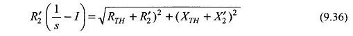
The maximum power output can then be found corresponding to the slip defined by Eq. (9.36). However, this condition corresponds to very low efficiency and very large current and is well beyond the normal operating region of the motor.
Limitation of Torque Slip Characteristics of Induction Motor:
The values of the circuit model parameters must be determined under conditions closely approximating the operating condition for which the model is to be used. Circuit model parameters valid for the normal operating condition would give erroneous results when used for abnormal values of slip. At starting, the motor draws many times the rated current resulting in saturation of core and consequent increase of the stator and rotor leakage reactances. Also the rotor frequency being high (same as stator), the rotor conductors present a higher resistance. Therefore parameters good for normal operating conditions would give a pessimistic result for starting current (larger than actual value) and starting torque.