Two Hole Directional Coupler:
It is often necessary to measure the power being delivered to load or an antenna through a transmission line. This is often done by a sampling technique, in which a known fraction of the power is measured, so that the total maybe calculated. It is imperative, under these conditions, that only the forward wave in the main line is measured, not the reflected wave (if any). A number of coupling units are used for such purposes and are known as Directional Coupler, the two hole directional coupler shown in Figure 7-19 being among the most popular. This Two Hole Directional Coupler is discussed because it is a good illustration of transmission-line techniques and has a direct waveguide counterpart.
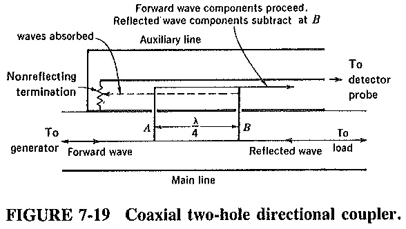
As indicated in Figure 7-19, the two hole directional coupler consists of a piece of transmission line to be connected in series with the main line, together with a piece of auxiliary line coupled to the main line via two probes through slots in the joined outer walls of the two coaxial lines. The probes do not actually touch the inner conductor of the auxiliary line. They couple sufficient energy into it simply by being near it. If they did touch, most of the energy (instead of merely a fraction) in the main line would be coupled into the auxiliary line; a fraction is all that is needed.
The probes induce energy flow in the auxiliary line which is mostly in the same direction as in the main line, and provision is made to deal with energy flowing in the “wrong” direction. The distance between the probes is λ/4 but may also be any odd number of quarter-wavelengths. The auxiliary line is terminated at one end by a resistive load. This, absorbs all the energy fed to it and is often termed a non-reflecting termination. The other end goes to a detector probe for measurement.
Any wave launched in the auxiliary line from right to left will be absorbed by the load at the left and will not, therefore, be measured. It now remains to ensure that only the forward wave of the main line can travel from left to right in the auxiliary line. The outgoing wave entering the auxiliary line at A, and proceeding toward the detector, will meet at B another sample of the forward wave. Both have traversed the same distance altogether, so that they add and travel on to the detector to be measured.
There will also be a small fraction of the reverse wave entering the auxiliary line and then travelling to the right in it. However small, this wave is undesirable and is removed here by cancellation. Any of it that enters at B will be fully canceled by a portion of the reflected wave which enters the auxiliary line at A and also proceeds to the right. This is so because the reflected wave which passes B in the main line enters the auxiliary line at A and then goes to B, having traveled through a distance which is 2 x λ/4 = λ/2 greater,than the reflected wave that entered at B. Being thus exactly 180° out of phase, the two cancel if both slots and probes are the same size and shape, and are correctly positioned.
Since various mechanical inaccuracies prevent ideal operation of this (or any other) directional coupler, some of the unwanted reflected wave will be measured in the auxiliary line. The directivity of a directional coupler is a standard method of measuring the extent of this unwanted wave. Consider exactly the same power of forward and reverse wave entering the auxiliary line. If the ratio of forward to reverse power measured by the detector is 30 dB, then the directional coupler is said to have a directivity of 30 dB. This value is common in practice.
The other important quantity in connection with a directional coupler is its directional coupling.
Directional Coupling is defined as the ratio of the forward wave in the main line to the forward wave in the auxiliary line.
It is measured in decibels, and 20 dB (100:1) is a typical value.