Digital Electronics Basics:
Digital devices are based on Digital Electronics Basics circuits which can represent two states, ON or OFF. The ability to design integrated circuits consisting of thousands of transistors on wafer-thin; postage-stamp-sized chips has made Digital Electronics Basics both feasible and extraordinarily powerful. The chants are used to store, evaluate, manipulate and modify digital code. Integrated circuitry has made it possible to design circuits that can handle large quantities of digitally encoded data at enormous speeds.
The Transistor Switch:
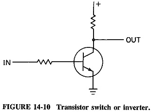
The fundamental circuit used with Digital Electronics Basics is the transistor switch, illustrated in Figure 14-10 in its simple form. If the base is held at a ground potential, the transistor will be cut off; i.e., no current will flow and the voltage at the collector will be equal to the value of the positive supply. When, however, the base is made positive, the transistor is turned on and current is conducted between the collector and emitter. The collector potential now assumes a voltage close to ground since the low resistance of the transistor forms a voltage divider with the collector resistance. The output, taken from the collector, will therefore be almost equal to the supply voltage when the base is grounded and almost at ground potential when a positive voltage is applied to the base. In typical digital terminology, the transistor forms an inverter, since its output is high when a low voltage is on its input, and vice versa.
Digital Gates:
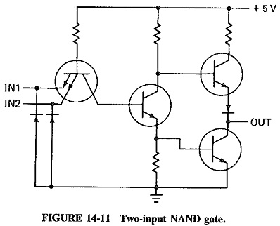
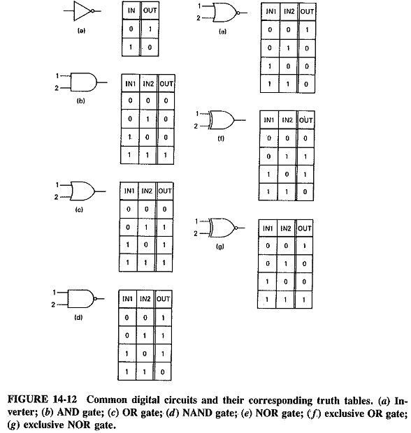
Another digital building block is the two-input NAND gate. This gate will provide a low output only when both inputs are high. Figure 14-11 is the schematic of a NAND gate from the digital family called transistor-transistor-logic (TTL). The NAND gate in the figure uses a “totem-pole” output stage which helps to speed up the transition from low to high. Other digital circuits are created from combinations of NAND gates and inverters. Some of the common Digital Electronics Basics are shown in Figure 14-12. The truth tables next to each of the logic diagrams indicate the actions of the gates. These basic gates are combined into more complex circuits needed for data processing.
The Flip-Flop:
One of the intermediate building blocks of data circuits is the flip-flop, or latch. The batch simply accepts an input consisting of either a high or a low, and then latches it onto its output. The latch will retain that level until different input data is received. The latch forms a simple memory device retaining data until the system requires it to be changed.
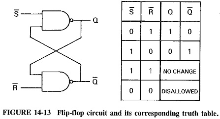
A simple flip-flop circuit can be constructed from NAND gates, as shown in Figure 14-13. Such circuits have been integrated, however, and designers usually choose the integrated devices.
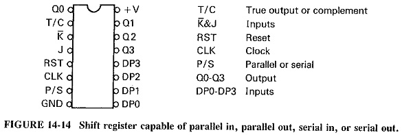
The Shift Register:
Figure 14-14 shows the diagram of a device called a shift register. It is composed of a series of latches so connected that they will successively accept data bits and retain them until the next bit is received. The shift register shown is capable of performing several functions. It can be loaded with data from its parallel inputs, and the data can then be clocked out of its serial output. The result is that a stream of parallel data bits is converted to a serial stream of successive data bits. In a similar manner, it is possible for the device to clock in a string of serial data bits through its serial input and then to make these bits available at its parallel outputs. These serial-to-parallel and parallel-to-serial conversions are important for data systems and data transmission. It should be noted that computer systems deal with data in a parallel form, although transmission systems most often require data to be in a serial form. Thus, in order for the computer data to be transmitted and then provided to other computer peripherals, it is normally necessary for serial-to-parallel and parallel-to-serial conversions to be made. Shift registers and similar devices will be noted as forming part of the data sets and other date transmission devices.
The Microprocessor:
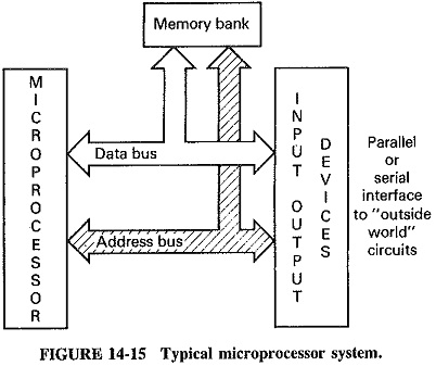
The microprocessor is a large-scale integrated circuit that has revolutionized computer technology. The microprocessor performs all the decision making and control functions necessary for computer operations. At the most elemental level, it is simply a combination of the gates and latches previously described. The power of the microprocessor results from the large number of gates which make up the device and the digital coding designed into it, which allow many decision options. Figure 14-15 is a block diagram of a typical microprocessor. The figure illustrates that the microprocessor is a bus-oriented device, i.e., it receives and sends out data as parallel binary words over common interconnections. All of the devices to which the microprocessor is connected share the data bus. Each device is permitted to use the data bus only when it is sending or receiving data.
The microprocessor has some latch circuits, called registers, built into it. Code words and data words are latched into these registers. Thousands of gates built into the microprocessor then cause different actions to take place, depending on the code and data words in the registers. The microprocessor performs its actions one at a time. It obtains an instruction from its program and places this in the control register. On the basis of the action that the instruction requires, the microprocessor will obtain data from, or will route data to, the other devices which make up the system. The peripheral devices are responsible for converting the incoming data into a form the microprocessor can use. When the appropriate data word is recognized, the microprocessor will carry out some action, e.g., addition, subtraction, storage and so on. This action is one step of data processing. Since the microprocessor can perform data manipulations very rapidly, processing of large quantities of data can be done even with small systems.
The microprocessor communicates with devices which “speak its language.” That is, devices used in a microprocessor system must be bus-oriented and must send and receive data as binary words. The use of binary words signifies that the microprocessor system requires parallel data. In an 8-bit system, all 8 bits would arrive at the data port of the system device at the same time. If data arrives at the data port 1 bit at a time, i.e., in serial form, it will be converted before delivery to the microprocessor.