Triggering in Digital Electronics | Types:
Triggering in Digital Electronics is the process of applying an external signal to induce transition from one state to another. The signal used for triggering is either a pulse of short duration or a step voltage. There are two processes of Triggering in Digital Electronics viz: Symmetrical and Unsymmetrical Triggering.
Unsymmetrical triggering is a process in which the signal is effective in inducing transition in only one direction. If reverse transition is to be introduced, a second triggering signal from a separate source has to be introduced in a different manner.
Symmetrical triggering is a process in which each successive triggering signal induces a transition, regardless of the state in which the binary happens to be. Thus symmetrical triggering requires one source to produce transition whereas in unsymmetrical triggering two separate sources are required.
Triggering in Digital Electronics signals may be applied at the output of a stage or the input of a stage. In case of transistors these signals may be applied at the collector or at the base of the transistor. Symmetrical triggering is used in binary-counting circuits and other applications. Unsymmetrical triggering is used in logic circuitry (in electronic registers, coding etc.) and is also used as a generator of a gate whose width equals the interval between triggers.
Unsymmetrical Triggering Through a Diode:
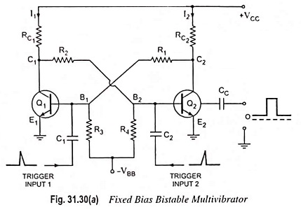
Refer to Fig. 31.30(a) and add the circuit shown in Fig. 31.38 at input stage and that in Fig. 31.39 at the output stage. Consider a stable state in which Q1 is “on” and Q2 is “off’.
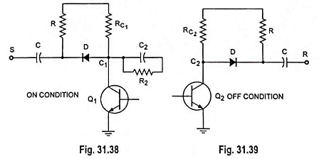
When Q1 is “on”, the diode D at the collector of Q1 is reverse biased by drop across RC1. The diode will not transmit a positive pulse and even the negative pulse cannot be transmitted unless it has an amplitude larger than this voltage drop which anyway cannot affect the state of Q2. Thus there can be no change in state due to the application of a pulse at the collector of Q1 when it is “on”. When Q2 is “off”, both anode and cathode of the diode at its collector are at VCC and so there is no voltage drop across diode D. The diode still fails to transmit a positive-going trigger, but will transmit a negative pulse or step to the base of Q1 which is “on”, and that will cause change in state. Thus in the assumed stable state, only a negative pulse impressed at ‘R’ can make change in state. The resistor R is required to be small enough so that any charge accumulating on capacitor C during the interval. when diode D conducts, will have time to decay during the time between pulses but it must be large enough to avoid the loading down of the trigger source. In case the triggering rate is high, then resistor R will have to be replaced by a diode.
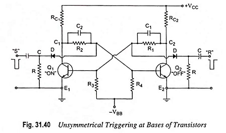
Figure 31.30(a) is redrawn for unsymmetrical triggering through a diode at the base of a transistor and is shown in Fig. 31.40. Here a negative pulse is applied to the base of the “on” stage through a diode. In case the available trigger amplitude is small, amplification of the input signal may become necessary before it is applied to the flip-flop. In such a case there will be no need of using diode, as the amplifier itself can provide the unilateral action for which diode is required.
Symmetrical Triggering Through Diodes:
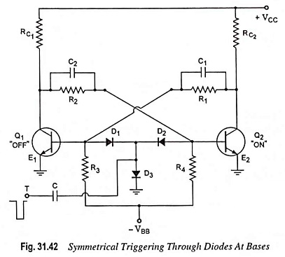
Figure 31.30(a) is redrawn for symmetrical triggering through diodes at the collectors and the bases and depicted in Figs. 31.41 and 31.42 respectively.
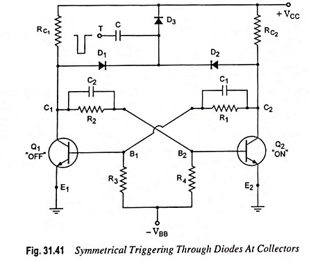
When Q2 is “on” and Q1 is “off”, in one of the stable states, diode D2 is reverse biased by supply voltage VCC and diode D1 is at zero bias as the collector of Q2 is at VCE(sat) and the collector of Q1 is at VCC. Thus a negative input signal will be transmitted to the collector of Q1 through diode D1 and, therefore, to the base of “on” stage Q2 via the combination R2C2 connecting the output of Q1 to the input of Q2. This negative pulse at the base of Q2 (which is “on”), turns it to the “off” state causing transition. After completion of this transition, diode D1 will be reverse biased and D2 will be at zero bias. The next negative pulse will pass through diode D2 instead of through diode D1. Hence these diodes are known as steering diodes.