Stator Protection:
Stator Protection – The type of stator faults likely to occur have been discussed already. The earth-fault current is usually limited by resistance in the neutral of the generator. Depending upon the amount of resistance in the neutral circuit of the generator the fault current may be limited to a value between 200A and 250A or between 4A and 10A. Resistor earthing is employed to get the former value whereas distribution transformer earthing is employed for the latter. This latter method has the advantage of ensuring minimum damage to the stator core, but it is not practicable when the stator winding is directly connected to the delta winding of the main transformer.
When the stator neutral is earthed through a resistor a CT is mounted in the generator neutral and connected to either an inverse time relay or an instantaneous attracted armature relay as shown in Fig. (6.12) depending on whether the generator is directly connected to the station bus bars or via a delta/star transformer.
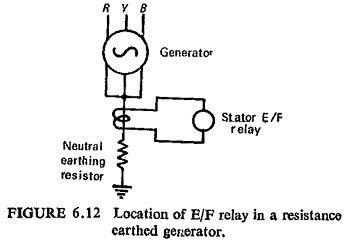
In the former case the inverse time relay will require grading with other earth-fault relays in the system. But in the latter case, because the earth-fault loop is restricted to the stator and transformer primary winding, no discrimination with other earth-fault relays is necessary. With resistor earthing it is impossible to protect 100% of the stator winding, the percentage of winding protected being dependent on the value of the neutral earthing resistor and the relay setting. In this case high-speed relays and breakers will be required to prevent damage. However the distributed capacitance of the stator to ground fixes a limit to the value of resistance necessary in the neutral circuit of the generator to prevent overvoltage due to resonance which might result in another winding fault. The maximum value of the resistance is given by
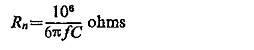
where C is the capacitance of the stator circuit to earth per phase in microfarad and f the system frequency.
If neutral is earthed through the primary winding of a distribution transformer, earth-fault protection is provided by connecting an over-voltage relay across its secondary, then the maximum value of resistance is equal to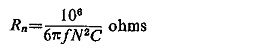
where N is the turn ratio of the transformer. In this case slow acting relays are sufficient to prevent damage.
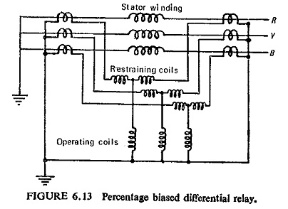
Generator Differential Protection: The best form of stator protection from phase-to-phase and phase-to-ground (iron lamination of the stator core) is provided by the longitudinal differential relay. The relay recommended for this application is an instantaneous attracted armature type setting 10 to 40% which is immune to a.c. transients and has the high speed feature is suitable if the CTs are reasonably matched. As is well known that if the CTs on the line side have dissimilar characteristics from those mounted at the neutral end of the winding, a relatively large spill current will flow through the relay operating coil, a percentage bias differential relay should be used under such circumstances. Longitudinal percentage biased differential protection for generator stator is shown in Fig. (6.13).
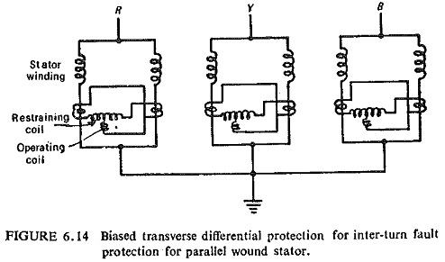
Stator Inter-turn Fault Protection: Inter-turn fault on the same phase of the stator winding does not disturb the balance between the currents in the neutral and the high voltage CTs; with the result that such a fault cannot be detected by longitudinal differential protection. Transverse differential protection can detect the unbalance between normally identical windings caused by an inter-turn fault when the generator has two windings per phase. Bias is used because the sharing will never be exact. Biased transverse differential protection to protect against inter-turn faults is shown in Fig. (6.14).
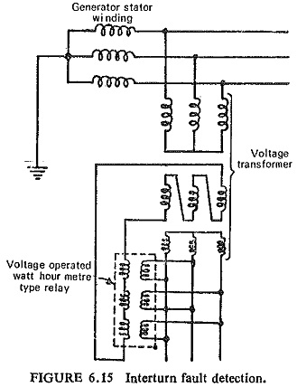
Generators having single winding per phase or those generators whose parallel windings are not accessible can be protected by using zero sequence component of voltage caused by the reduction of emf in the faulted phase. One such circuit is shown in Fig. (6.15) where the zero sequence voltage appears across the tertiary winding of the voltage-transformer which is connected to the operating winding of the three element directional relay. The winding in quadrature to this operating winding of the relay is energized by the secondary of the voltage-transformer.