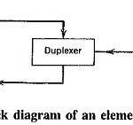
Basic Radar System Block Diagram
Basic Radar System Block Diagram: Basic Radar System Block Diagram consists of a transmitter and a receiver, each connected to a directional antenna. The transmitter is capable of sending out…
Continue Reading
Basic Radar System Block Diagram