Reactive Power and The Power Triangle:
We know that the average power dissipated is
![]()
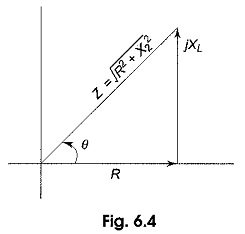
From the impedance triangle shown in Fig. 6.4
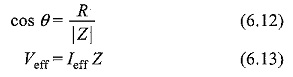
If we substitute Eqs (6.12) and (6.13) in Eq. (6.11), we get
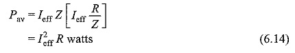
This gives the average power dissipated in a resistive circuit.
If we consider a circuit consisting of a pure inductor, the power in the inductor
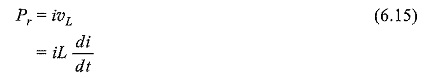
Consider
![]()
Then
![]()
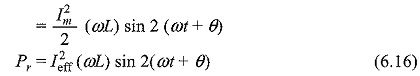
From the above equation, we can say that the average power delivered to the circuit is zero. This is called reactive power. It is expressed in volt-amperes reactive (VAR).
![]()
From Fig. 6.4, we have
![]()
Substituting Eq. 6.18 in Eq. 6.17, we ge
The Power Triangle:
A generalized impedance phase diagram is shown in Fig. 6.5. A phasor relation for power can also be represented by a similar diagram because of the fact that true power Pav and reactive power Pr differ from R and X by a factor I2eff, as shown in Fig. 6.5.
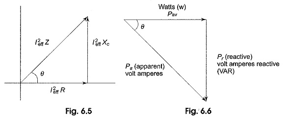
The resultant power phasor I2eff Z, represents the apparent power Pa.
At any instant in time, Pa is the total power that appears to be transferred between the source and reactive circuit. Part of the apparent power is true power and part of it is reactive power.
![]()
The power triangle is shown in Fig. 6.6.
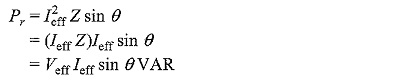
From Fig. 6.6, we can write
![]()
or average power Pav = Pa cos θ
and reactive power Pr= Pa sin θ