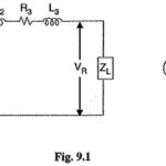
Electrical Design of Overhead Lines Articles:
Constants of a Transmission Line: A transmission line has resistance, inductance and capacitance uniformly distributed along the whole length of the line. Before we pass on to the methods of finding these Constants of a Transmission Line, it is profitable to … (Read More)
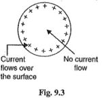
Skin Effect in Transmission Lines: Skin Effect in Transmission Lines – When a conductor is carrying steady direct current (d.c.), this current is uniformly distributed over the whole X-section of the conductor. However, an alternating current flowing through the conductor does … (Read More)
Flux Linkage: The inductance of a circuit is defined as the flux linkage per unit current. Therefore, in order to find the inductance of a circuit, the determination of flux linkage is of primary importance. We shall discuss two important cases … (Read More)
Inductance of Single Phase Two Wire System: A Inductance of Single Phase Two Wire System consists of two parallel conductors which form a rectangular loop of one turn. When an alternating current flows through such a loop, a changing magnetic flux … (Read More)
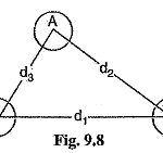
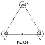
Inductance of 3 Phase Overhead Line: Fig. 9.8 shows the three conductors A, B and C of a Inductance of 3 Phase Overhead Line carrying currents IA, IB and IC respectively. Let d1, d2 and d3 be the spacings between the conductors … (Read More)
Self GMD and Mutual GMD: Self GMD and Mutual GMD – The use of self geometrical mean distance (abbreviated as Self GMD) and mutual geometrical mean distance (Mutual GMD) simplifies the inductance calculations, particularly relating to multiconductor arrangements. The symbols used … (Read More)
Electric Potential Definition: The Electric Potential point due to a charge is the work done in bringing a unit positive charge from infinity to that point. The concept of electric potential is extremely important for the determination of capacitance in a … (Read More)
Capacitance of a Single Phase Two Wire Line: Consider a Capacitance of a Single Phase Two Wire Line consisting of two parallel conductors A and B spaced d metres apart in air. Suppose that radius of each conductor is r metres … (Read More)
Capacitance of Three Phase Overhead Line: In a Capacitance of Three Phase Overhead Line, the capacitance of each conductor is considered instead of capacitance from conductor to conductor. Here, again two cases arise viz., symmetrical spacing and unsymmetrical spacing. 1.Symmetrical Spacing: Fig. … (Read More)