Radar Systems Articles:
Basic Radar System Block Diagram: Basic Radar System Block Diagram consists of a transmitter and a receiver, each connected to a directional antenna. The transmitter is capable of sending out a large UHF or microwave power through the antenna. The receiver … (Read More)
Radar Performance Factors: Quite apart from being limited by the curvature of the earth, the maximum range of a radar Set depends on a number of other Radar Performance Factors. These can now be discussed, beginning with the classical radar range … (Read More)
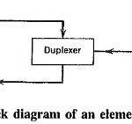
Pulsed Radar System Block Diagram: A very Pulsed Radar System Block Diagram set was shown in Figure 16-1. A more detailed block diagram will now be given, and it will then be possible to compare some of the circuits used with … (Read More)
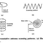
Antenna Scanning Methods: Radar antennas are often made to scan a given area of the surrounding space, but the actual scanning pattern depends on the application. Figure 16-6 shows some typical Antenna Scanning Methods. The first of these is the simplest but … (Read More)
Antenna Tracking System: Having acquired a target through a scanning method as just described, it may then be necessary to locate it very accurately, perhaps in order to bring weapons to bear upon it. Having an antenna with a narrow, pencil-shaped … (Read More)
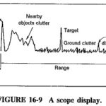
Display Methods in Radar System: The output of a radar receiver may be displayed in any of a number of ways, the following three being the most common Display Methods in Radar System are: Deflection Modulation of a cathode-ray-tube screen as … (Read More)
Pulsed Radar Systems: A Pulsed Radar Systems is generally required to perform one of two tasks: It must either search for targets or else track them once they have been acquired. Sometimes the same radar performs both functions, whereas in other … (Read More)
Doppler Effect in Radar: The apparent frequency of electromagnetic or sound waves depends on the relative radial motion of the source and the observer. If source and observer are moving away from each other, the apparent frequency will decrease, while if … (Read More)
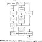
Moving Target Indicator Radar Block Diagram: Basically, the Moving Target Indicator Radar Block Diagram compares a set of received echoes with those received during the previous sweep. Those echoes whose phase has remained constant are then cancelled out. This applies to … (Read More)
Radar Beacons: A Radar Beacons is a small radar set consisting of a receiver, a separate transmitter and an antenna which is often omnidirectional. When another radar transmits a coded set of pulses at the beacon, i.e., interrogates it, the beacon … (Read More)
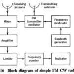
Frequency Modulated Continuous Wave Radar: The greatest limitation of Doppler radar, i.e., its inability to measure range, may be overcome if the transmitted carrier is Frequency Modulated Continuous Wave Radar. If this is done, it should be possible to eliminate the … (Read More)
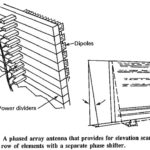
Phased Array Radars: Introduction With some notable exceptions, the vast majority of radars have to cover an area in searching and/or tracking, rather than always being pointed in the same direction. This implies that the antenna will … (Read More)
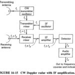
CW Doppler Radar Block Diagram: A simple CW Doppler Radar Block Diagram, such as the one shown in Figure 16-14, sends out continuous sine waves rather than pulses. It uses the Doppler effect to detect the frequency change caused by a … (Read More)