Polyphase Circuits

Effects of Harmonics

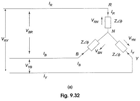
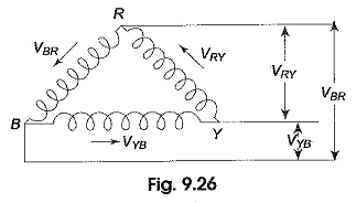
Effects of Harmonics: The relationship between line and phase quantities for wye and delta connections as derived earlier are strictly valid only if the source voltage is purely sinusoidal. Such a waveform is an ideal one. Modern alternations are designed to give a terminal voltage which is almost sinusoidal. But it is nearly impossible to […]

Effects of Harmonics Read More »

Reactive Power with Wattmeter

Reactive Power with Wattmeter: We have already seen earlier that the difference between higher reading wattmeter and lower reading wattmeter yields VLIL sin Φ. So, the total reactive power = √3 VLIL sin Φ. Reactive Power with Wattmeter in a balanced three-phase load can also be calculated by using a single wattmeter. As shown in

Reactive Power with Wattmeter Read More »

Leading Power Factor Load

Leading Power Factor Load: Suppose the load in Fig. 9.46(a) is capacitive, the wattmeter connected in the leading phase would read less value. In that case, WR will be the lower reading wattmeter, and WY will be the higher reading wattmeter. Figure 9.48 shows the phasor diagram for the Leading Power Factor Load. As the

Leading Power Factor Load Read More »

Power in Three Phase Circuits

Power in Three Phase Circuits: Measurement of power by a wattmeter in a single phase circuit can be extended to measure Power in Three Phase Circuits. From earlier Section, it is clear that we require three wattmeters, one in each phase to measure the power consumed in a three-phase system. Obviously, the total power is

Power in Three Phase Circuits Read More »

Three Phase Balanced Circuit

Three Phase Balanced Circuit: The analysis of Three Phase Balanced Circuit is presented in this section. It is no way different from the analysis of AC systems in general. The relation between voltages, currents and power in delta-connected and star-connected systems has already been discussed in earlier section. Balanced Three-Phase System-Delta Load: Figure 9.31(a) shows

Three Phase Balanced Circuit Read More »

3 Phase Delta Connection

3 Phase Delta Connection: Delta Connected System – Figure 9.26 shows a balanced three-phase, three-wire, delta-connected system. This arrangement is referred to as mesh connection because it forms a closed circuit. It is also known as 3 Phase Delta Connection because the three branches in the circuit can also be arranged in the shape of

3 Phase Delta Connection Read More »

Scroll to Top