Carrier Pilot Protection and Microwave Pilot Protection:
The problem of providing economically an auxiliary channel by means of pilots for long lines directed attention to carrier techniques. In this case the power line itself is used as the channel for carrying information between the two ends of the transmission line. Two different types of communication channels presently are Carrier Pilot Protection and Microwave Pilot Protection.
(a) Carrier-Current Channel: High frequency signals in the range of 50 kHz to 400 kHz commonly known as the carrier are transmitted over the conductors of the protected line. To inject the carrier signal and to restrict it within the protected section of the line suitable coupling apparatus and line traps are employed at both ends of the protected section. This obviously makes it quite expensive and justifies its application only on transmission lines of 110 KV and above. The main application of power line carrier has been for the purpose of supervisory control, telephone communication, telemetering and relaying.
(b) Microwave Channel: It uses ultra high frequency. (450 MHz to 10,000 MHz) transmitter-receiver system for connecting the relaying equipment located at the terminals of the protected line. The communication channel is space in this case; thus the line need not be fitted with additional equipment. Transmission is generally by line of sight and this must take into account the curvature of the earth and topology of the route over which transmission is taking place. This limits the maximum length of the simplest microwave channel to about 40 to 60 km. Channels for long transmission lines use radio relaying techniques; or, in other words, the signals are beamed by antennas from point to point like TV signals.
Carrier Pilot Protection are commonly used for the protection of transmission lines and will be considered hereafter. Microwave protection has similar relaying equipment and operating principles as the Carrier Pilot Protection except the channel used for communication.
Advantages of Carrier-Current Channel: High-frequency signal transmission along overhead power lines offers the following advantages over pilot wires:
- No separate wires are needed for signalling, as the power lines themselves carry power as well as communication signals. Hence the capital and running costs are lower.
- Transmission path is fully controlled by the operating authority.
- Carrier signals suffer much less attenuation on power lines than on usual telephone lines on account of very low resistance of power lines compared to telephone lines.
- Large spacing between conductors of power lines reduces capacitance which results in smaller attenuation at high frequencies.
- The transmission medium is robust and therefore reliable.
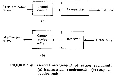
The general arrangement of carrier equipment is shown in Fig. (5.41). Transmission instructions are initiated from the protective relays via a control circuit and, conversely, received by the protection relays via a carrier receive relay.
Carrier Equipment: The main elements of the carrier channel are: (i) transmitter, (ii) receiver, (iii) coupling equipment, and (iv) line trap.
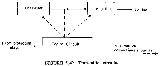
(i) Transmitter: The transmitter consists of an oscillator and an amplifier shown in Fig. (5.42). The oscillator generates a frequency signal within 50-500 kHz frequency band. The amplifier provides sufficient radio frequency power (5-40 W) at the operating frequency to overcome losses in the transmission channel between the terminals and to operate the receiver at the remote end. The transmitter control can be effected in various ways shown by dotted arrows in Fig. (5.42). The transmitter is thus required to modulate the carrier with protective signals. The modulation process usually involves taking one half cycle of 50 Hz signal and using this to create blocks of carrier.
(ii) Receiver: The receiver usually consists of an attenuator matching transformer, band-pass filter and amplifier-detector as shown in Fig. (5.43a).
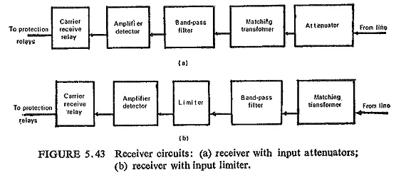
The amplifier detector converts a small incoming signal into a signal capable of operating a relatively insensitive carrier receive relay. The matching transformer is necessary to match the low characteristic impedance of the line on one side and a high input impedance of the amplifier-detector on the other. In case of short lines limiting of signal input to the amplifier-detector is necessary to avoid overloading as shown in Fig. (5.43b).
The transmitters and receivers at the two ends of the protected section are tuned to the same frequency so that each receiver responds to local as well as far end transmitters.
(iii) Coupling equipment: Coupling of the high frequency transmitter-receiver units to the power line is done through high-voltage capacitors used in conjunction with drainage coils. The high voltage coupling capacitor which has a capacitance of about 0.001 μF is earthed through the drainage coil having inductance of about 100 mH. This provides isolation of the terminal equipment from the power line by providing a very high impedance to power frequency currents and a low impedance to carrier frequency currents. For matching the transmitter and the receiver units to the coupling capacitors and the power line, connecting filters are provided. These filters are normally adjustable air cored transformers with capacitors connected in series with their tune coils. The connection of transmitter-receiver units to the connecting filters is done through coaxial cables. A typical schematic diagram of carrier-current pilot relay system is shown in Fig. (5.44).
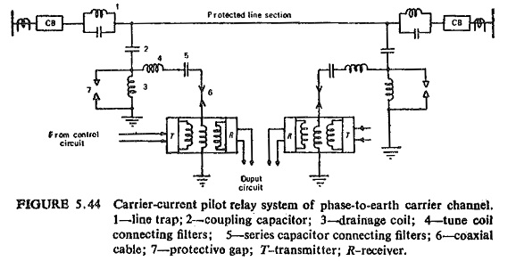
It can be seen that the path for carrier current is through the line conductor, coupling capacitor, connecting filter, coaxial cable and ground, while the power frequency current can flow through the line conductor only. Protective gap protects the high frequency system from line surges and is also used for earthing the coupling capacitor to permit maintenance and inspection of the connecting filter.
(iv) Line trap: Rejection filters known as line traps consisting of a parallel resonant circuit (L and C in parallel) tuned to the carrier frequency are connected in series at each end of the protected line. Such a circuit offers high impedance to the flow of carrier frequency currents thus preventing the dissipation of the carrier signal in the neighbouring sections. It also reduces the interference with the neighbouring carrier channels.
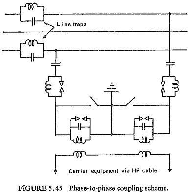
Method of Coupling: Coupling may be either of one phase conductor with earth return, i.e. phase-to-earth coupling, or it may comprise two couplings, one to each of the two phase conductors called phase-to-phase coupling. The phase-to-earth coupling is quite popular on account of its lower cost as it requires only half as many coupling capacitors and wave traps that would be needed for phase-to-phase coupling. Phase-to-phase coupling is superior because of its lower attenuation and lower interference levels than the phase-to-earth coupling, and is preferred for better communication characteristics. Phase-to-phase coupling scheme for one end of the protected three-phase line is shown in Fig. (5.45).
Carrier Circuits for Protection: There are two basic forms of carrier protection schemes: (a) directional comparison protection, and (b) phase comparison protection.
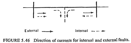
(a) Directional Comparison Protection: The direction of current flow is compared at the two ends of the protected section by means of directional relays. The conditions for internal and external faults are shown in Fig. (5.46). The relays at both the ends of the protected section respond to fault power flowing away from the bus (tripping direction). For faults in the protected section, power flows in the tripping direction at both ends. Power flows in opposite directions for external faults. A simple signal through the Carrier Pilot Protection is transmitted from one end to the other during faults.
The pilot scheme can be used for transmitting either blocking, or permitting signals. Hence two types of protection are possible:
- Carrier-blocking scheme, in which the presence of carrier prevents or blocks operation of the protection. Carrier Pilot Protection is therefore transmitted only upon the occurrence of a fault and is used to prevent tripping in the event of an external fault.
- Carrier-permitting scheme, in which the presence of carrier permits operation of the protection.
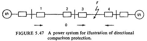
The directional comparison method of relay protection is illustrated by means of Fig. (5.47). The operation of the directional element provided on each breaker is indicated by the arrow and the nonoperation by the letter 0. Abnormal conditions existing on the occurrence of a fault activate relays on each of the breakers near the fault. These relays unless blocked from operation, cause tripping of the breakers. The blocking signal is controlled by the directional relays on each breaker, and is transmitted from one end of a protected section to the other by carrier. If a directional element determines that the fault is not in the protected section, a signal is transmitted which blocks breaker operation at both ends of the section. If the directional elements at both ends show that the fault is in the protected section, no blocking signal is transmitted from either end, and both breakers trip. The sequence of events for a fault at F is made clear by a study of Fig. (5.47).
At breaker 1 the directional element shows that the fault may be in the section 1-2. This breaker trips if no blocking signal is received. No blocking signal is transmitted to breaker 2.
At breaker 2 the directional element shows that the fault is not in the section 1-2. A carrier signal is transmitted which blocks tripping of both the breakers 1 and 2.
At breaker 3 the directional element shows that the fault may be in the section 3-4. No blocking signal is transmitted. Similarly at breaker 4 the directional element shows that the fault may be in the section 3-4 and hence no blocking signal is transmitted. After a very short time delay (1 to 3 cycles), both the breakers 3 and 4 trip.
The carrier-blocking scheme provides more reliable, operation than the carrier-permitting scheme. This is because a failure in the carrier-permitting signal equipment will mean a failure in isolating the fault, whereas a failure in the carrier-blocking signal equipment isolates the section on which no fault exists. However, this type of false operation is preferable to the failure to clear a faulted section.
Carrier-aided distance protection: The directional comparison Carrier Pilot Protection schemes presently used are built around standard 3-zone step-type distance relays. This enables to speed up fault clearance for internal zone 2 faults. The carrier channel is used either to transmit a stabilizing signal preventing tripping of a remote circuit breaker in the event of a local external zone 2 fault, or to provide a tripping signal in the event of an internal zone 2 fault. The principal features of plain 3-zone distance scheme are illustrated in Fig. (5.48).
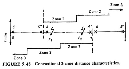
Carrier signalling is concerned with the end zones of a protected section (AA’). Faults at points F1 and F2 will be considered. Fault at F1 will be seen at end A in zone 1 and at end A’ in zone 2. Similarly a fault at F2, will be seen at end A’ in zone 1 and at end A in zone 2.
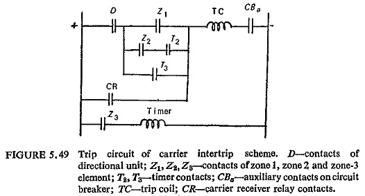
Transfer trip or intertrip technique is adopted to speed up the fault clearance at the end which clears the fault in zone 2. This is achieved by controlling the carrier transmitter and a carrier receive relay by zone 1 contact. For a fault at F1 the zone 1 relay at A initiates a carrier signal in addition to completing the zone 1 trip circuit of this end. Carrier signal when received at end A’ trips it immediately by shunting the zone 2 timer Contacts with the help of a carrier receive relay. A fault at F2 is cleared in a similar way. The tripping circuit of the conventional distance scheme as modified by the carrier intertrip is shown in Fig. (5.49).
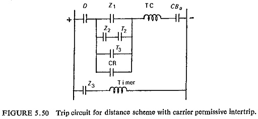
It can be seen that the carrier is transmitted over a faulty section and thus the required strength of the carrier signal may not be received on the other end due to attenuation introduced into the transmission path by the fault. Further, during external fault conditions the receiver may operate because of noise generated within the protected section and undesirable tripping may result. This difficulty is partly overcome by monitoring the carrier receive relay by the fault detector, so that the carrier receive relay performs its function during a genuine internal fault condition. Such an arrangement is shown in Fig. (5.50) and is described as ‘permissive intertrip.’
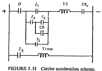
If the zone 2 timer contacts are shorted by a normally open carrier receive relay in parallel then all the faults in the protected section can be cleared approximately in first zone time. This is illustrated in Fig. (5.51) and such a scheme is known as Carrier acceleration scheme.