Busbar Arrangements in Substations:
Busbar are the important components in a sub-station. There are several Busbar Arrangements in Substations that can be used in a sub-station. The choice of a particular arrangement depends upon various factors such as system voltage, position of sub-station, degree of reliability, cost etc. The following are the important bus-bar arrangements used in sub-stations :
(i) Single bus-bar system: As the name suggests, it consists of a single bus-bar and all the incoming and outgoing lines are connected to it. The chief advantages of this type of arrangement are low initial cost, less maintenance and simple operation. However, the principal disadvantage of single bus-bar system is that if repair is to be done on the bus-bar or a fault occurs on the bus, there is a complete interruption of the supply. This arrangement is not used for voltages exceeding 33kV. The indoor 11kV sub-stations often use single Busbar Arrangements in Substations.
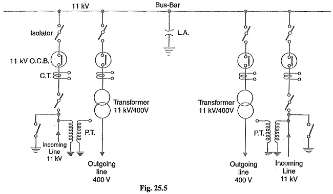
Fig. 25.5 shows single Busbar Arrangements in Substations. There are two 11 kV incoming lines connected to the bus-bar through circuit breakers and isolators. The two 400V outgoing lines are connected to the bus bars through transformers (11kV/400 V) and circuit breakers.
(ii) Single bus-bar system with sectionalisation: In this arrangement, the single bus-bar is divided into sections and load is equally distributed on all the sections. Any two sections of the bus-bar are connected by a circuit breaker and isolators. Two principal advantages are claimed for this arrangement. Firstly, if a fault occurs on any section of the bus, that section can be isolated without affecting the supply from other sections. Secondly, repairs and maintenance of any section of the bus-bar can be carried out by de-energising that section only, eliminating the possibility of complete shut down. This arrangement is used for voltages upto 33 kV.
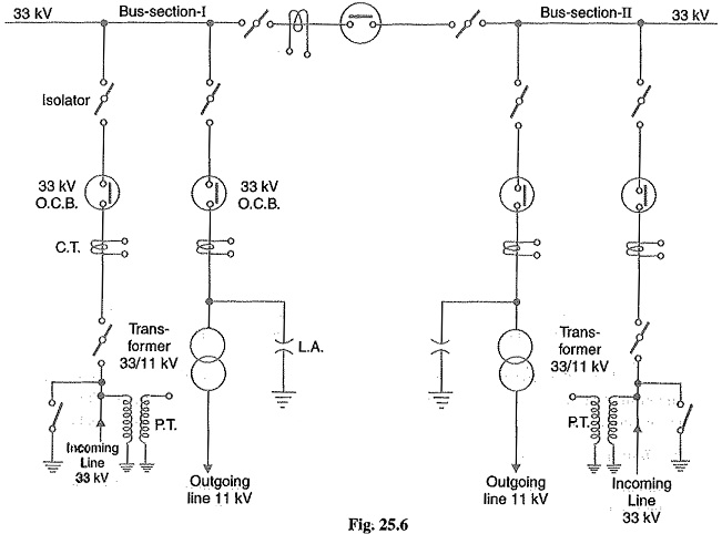
Fig. 25.6 shows bus-bar with sectionalisation where the bus has been divided into two sections. There are two 33 kV incoming lines connected to sections I and II as shown through circuit breaker and isolators. Each 11 kV outgoing line is connected to one section through transformer (33/11 kV) and circuit breaker. It is easy to see that each bus-section behaves as a separate bus-bar.
(iii) Duplicate bus-bar system: This system consists of two bus-bars, a “main” bus-bar and a “spare” bus-bar. Each bus-bar has the capacity to take up the entire sub-station load. The incoming and outgoing lines can be connected to either bus-bar with the help of a bus-bar coupler which consists of a circuit breaker and isolators. Ordinarily, the incoming and outgoing lines remain connected to the main bus-bar. However, in case of repair of main bus-bar or fault occurring on it, the continuity of supply to the circuit can be maintained by transferring it to the spare bus-bar. For voltages exceeding 33kV, duplicate bus-bar system is frequently used.
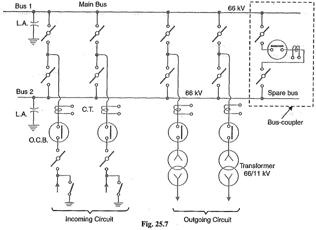
Fig. 25.7 shows the arrrangement of duplicate bus-bar system in a typical sub-station. The two 66kV incoming lines can be connected to either bus-bar by a bus-bar coupler. The two 11 kV outgoing lines are connected to the bus-bars through transformers (66/11 kV) and circuit breakers.
Terminal and Through SubStations:
All the transformer sub-stations in the line of power system handle incoming and outgoing lines. Depending upon the manner of incoming lines, the sub-stations are classified as :
-
Terminal sub-station
-
Through sub-station
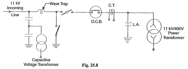
1. Terminal sub-station: A terminal sub-station is one in which the line supplying to the substation terminates or ends. It may be located at the end of the main line or it may be situated at a point away from main line route. In the latter case, a tapping is taken from the main line to supply to the sub-station. Fig. 25.8 shows the schematic connections of a terminal sub-station. It is clear that incoming 11 kV main line terminates at the sub-station. Most of the distribution sub-stations are of this type.
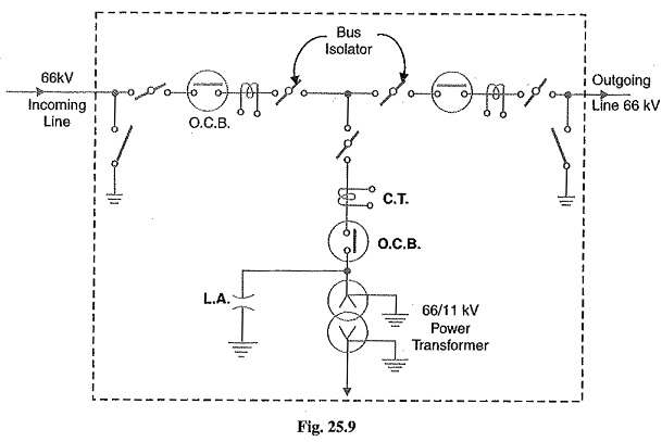
2. Through sub-station: A through sub-station is one in which the incoming line passes `through’ at the same voltage. A tapping is generally taken from the line to feed to the transformer to reduce the voltage to the desired level. Fig. 25.9 shows the schematic connections of a through substation. The incoming 66 kV line passes through the sub-station as 66kV outgoing line. At the same time, the incoming line is tapped in the sub-station to reduce the voltage to 11 kV for secondary distribution.