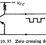
Zero Crossing Detector Circuit
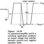
Zero Crossing Detector Circuit: Zero Crossing Detector Circuit basically involves the sine to square wave conversion by a level detector circuit followed by a pulse circuit, which consists of one…
Continue Reading
Zero Crossing Detector Circuit