RC Integrator Circuit Diagram and its Application
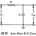
RC Integrator Circuit Diagram and its Application: A circuit that gives an output voltage directly proportional to the integral of its input is known as integrating circuit. Figure 29.18 shows…
Summing Integrator Circuit: Many useful circuits can be designed using the basic integrator circuit. One of such useful circuits is the Summing Integrators. It can be obtained by applying more…
Op Amp Integrator Circuit: In an Op Amp Integrator Circuit, the output voltage is the integration of the input voltage. The integrators circuit can be obtained without using active devices…
Low Pass RC Circuit Diagram, Derivation and Application: The Low Pass RC Circuit is shown in Fig. 29.18. In a Low Pass RC Circuit, the output voltage vout is taken…
Darlington Amplifier - Circuit Diagram, Characteristics, Merits and Applications: Darlington amplifier with voltage divider bias is shown in Fig. 19.50. In this circuit the output of one amplifier is coupled…
Miller Sweep Circuit and Miller Bootstrap Sweep Circuit: The basic R-C sweep circuit is shown in Fig. 30.134, in which opening of switch S provides sweep voltage, as already explained…
OTA Adder (Summer) and OTA Lossy Integrator: OTA Adder (Summer) : OTA adder is shown in Fig. 41.9 for which the output voltage is given as where G = 1/R.…
TV Receiver Synchronizing Circuits: The task of the TV Receiver Synchronizing Circuits is to process received information, in such a way as to ensure that the vertical and horizontal oscillators…