Types of Electrical Drives:
Types of Electrical Drives has the following major parts: load, motor, power modulator, control unit and source. There are large number of loads and each load has its own specific requirements. Some common aspects to loads are discussed and specific requirements of some common loads in later chapters. Here we examine four Types of Electrical Drives; viz. motors, power modulators, sources and control unit.
Electrical Motors
Motors commonly used in Types of Electrical Drives are: dc motors–shunt, series, compound and permanent magnet; Induction motors—squirrel-cage, wound rotor and linear; Synchronous motors—wound field and permanent magnet; Brushless dc motors; Stepper motors; and Switched reluctance motors.
In the past, induction and synchronous motors were employed mainly in constant speed drives. Variable speed drives consisting these machines were either too expensive or had very poor efficiency. Consequently, variable speed drive applications were dominated by dc motors.
ac motors are now employed in variable speed drives also due to development of semiconductor converters employing thyristors, power transistors, IGBTs and GTOs.
Due to presence of commutator and brushes dc motors have a number of disadvantages as compared to ac motors (induction and synchronous motors): higher cost, weight, volume and inertia for the same rating, need for frequent maintenance, unsuitable for explosive and contaminated environments and restrictions on maximum voltage, speed and power ratings. Squirrel-cage induction motor, which costs nearly one-third of a dc motor of the same rating, is extremely rugged, requires practically no maintenance and can be built for higher speeds, torques and power ratings. Wound-rotor motors are more expensive than squirrel-cage motors. Their maintenance needs, although more than squirrel-cage motors, are much less compared to dc motors. They are also available in high power ratings. Wound field and permanent magnet synchronous motors have a higher full load efficiency and power factor than induction motors. Wound field motors can be designed for a higher power rating than induction motors. However, compared to squirrel-cage induction motors they have higher cost and size for the same rating and require more maintenance. The permanent magnet synchronous motors have all the advantages of squirrel-cage induction motors except that they are available in lower power ratings.
Because of numerous advantages of ac motors described above, ac drives have succeeded in replacing dc drives in a number of variable speed applications.
Brushless dc motor is somewhat similar to a permanent magnet synchronous motor, but has lower cost and requires simpler and cheaper converter. It is being considered for low power high speed drives and for servo applications, as an alternative to dc servo motor which has been very popular so far. The dc servo motor motor has all the disadvantages of commutator and brushes listed above. At low power levels, the coulomb friction between the brushes and commutator is objectionable, as it adversely affects the steady state accuracy of the drive.
Recently, stepper motor has become popular for position control and switched reluctance motor drive for speed control.
Power Modulators
It is difficult to classify power modulators. A somewhat satisfactory classification is:
(a) Converters;
(b) Variable impedances and
(c) Switching circuits.
Some drives may employ more than one of these modulators. Those power modulators which are employed in industrial drives will be discussed.
(a) Converters
When a power modulator performs function (iii) (see Sec. 1.1), it can be classified as converter. Usually, a converter also performs function (i) in addition to (ii). Depending on the circuit, it may also be able to perform function (iv) of the power modulator. Need for a converter arises when nature of the available electrical power is different than what is required for the motor. Power sources are usually of the following types:
- Fixed voltage and fixed frequency ac
- Fixed voltage dc.
For the control of dc motors one requires variable dc voltage whereas for ac motors one requires either fixed frequency variable voltage ac or variable frequency variable voltage ac. These motor requirements are met by the following converters and their combinations:
1.ac to dc Converters:
ac-dc converters are shown in Fig. 1.2. The converter of Fig. 1.2(a) is used to get dc supply of fixed voltage. from the ac supply of fixed voltage. Such a converter is known as uncontrolled rectifier. Converters, of Fig. 1.2(b) to (j) allow a variable voltage dc supply to be obtained from the fixed voltage ac supply. In converters of Figs. I.2(b) and (c), a stepless variation of output voltage can be achieved by controlling firing angle of converter thyristors by low power signals from a control unit. Converter of Fig. 1.2(b) is a two quadrant converter in the sense that it is capable of providing variable dc voltage of either polarity with positive current. However, converter of Fig. 1.2(c) is a single-quadrant converter (positive voltage and current). Converters of Fig. 1.2(b) and (c) produce harmonics both on dc and ac side and have low power factor for low dc voltages. The converters of Fig. 1.2(d), (e) and (f) operate at unity fundamental power factor.
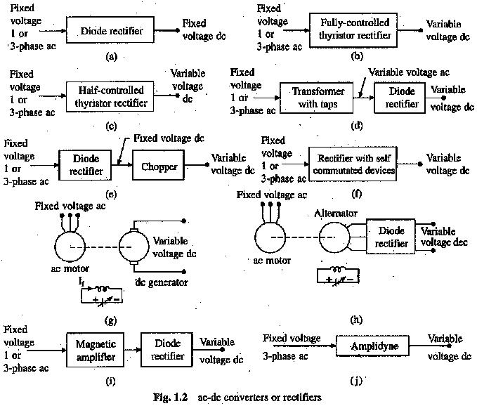
The output voltage in converter 1.2(d) is changed by applying mechanical force. Few discrete steps of dc voltage can only be obtained. In converter of Fig. 1.2(e) output voltage can be varied steplessly by controlling the duty ratio of semiconductor devices of the chopper by low power electrical signals from a control unit. The converter of Fig. 1.2(0 is a controlled rectifier employing self-commutated device such as power transistors, IGHTs and GTOs. It can be a single or two quadrant converter depending on the circuit. When connected in antiparallel, converters of Figs. 2(b) and (f) can provide four quadrant operation (variable voltage and current of either polarity). In ac to dc converter of Fig. 1.2(g),. the output voltage can be controlled by controlling field current of the generator from a control unit (amplifier) of higher power level than the control units of converters of Figs. 1.2(b), (c), (e) and (0. This can operate in all four quadrants. Because of the two rotating machines, it has a number of disadvantages: bulky, heavy, noisy, less efficient, slow response, expensive and requires special foundation. Disadvantages associated with commutator and brushes of file dc generator (Fig. 1.2(g)) are removed in converter of Fig: 1.2(h). However, this converter can operate in a single quadrant only. Some very old equipments may also employ ac to dc converter of Figs. 1.2(i) and (j) employing magnetic amplifier and amplidyne respectively. Magnetic amplifiers and amplidynes are controlled from low power dc signals.
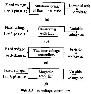
2.AC Voltage Controllers or AC Regulators:
ac voltage controllers (Fig. 1.3) are employed to get variable ac voltage of the same frequency from a source of fixed ac voltage. Voltage controller of Fig. 1.3(a) gives a fixed (smaller) ac voltage supply. The autotransformers capable of giving variable output voltage are not employed due to sliding contacts. Variable ac voltage with few discrete steps is obtained from the controller of Fig. 1.3(b). The control is exercised by a mechanical force. The output voltage and source current are sinusoidal. Converter of Fig. 1.3(c) employs a thyristorised voltage controller. Stepless control of the output voltage can be obtained by controlling firing angle of converter thyristors by low power signals from a control unit. Output voltage and source current have harmonics and power factor is poor at low output voltages. Few old drives may employ magnetic amplifier to get variable voltage ac from fixed voltage ac. Because of high cost, weight and volume, and poor efficiency they have been replaced by thyristor voltage controllers in almost all applications.
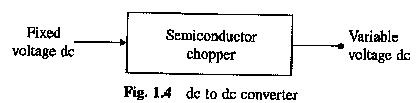
3.Choppers or dc-dc Converters (Fig. 1.4):
They are used to get variable voltage dc from a fixed voltage dc and are designed using semiconductor devices such as power transistors, IGBTs, GTOs, power MOSFETs and thyristors. Output voltage can be varied steplessly by controlling the duty ratio of the device by low power signals from a control unit.
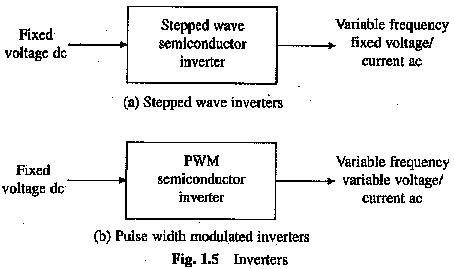
4.Inverters:
Inverters are employed to get a variable frequency as supply from a dc supply. Stepped-wave inverters of Fig. 1.5(a) can be designed to behave as voltage source or current source. Accordingly they are known as voltage source or current source inverters. For the control of ac motor, voltage/current should also be controlled along with frequency. Variation in output voltage/current can be achieved by varying the input dc voltage. This is achieved either by interposing a chopper in between fixed voltage dc source and the inverter or the inverter may be fed from an ac-dc converter from among those of Figs. 1.2(b), (c) or (f). Output voltage and current have stepped waveform, consequently they have substantial amount of harmonics. Variable frequency and variable voltage ac is directly obtained from fixed voltage dc when the inverter is controlled by pulse-width modulation (PWM) (Fig. 1.5(b)). The PWM control also reduces harmonics in the output voltage. Inverters are built using semiconductor devices such as thyristors, power transistors, IGBTs, GTOs and power MOSFETs.. They are controlled by, firing pulses obtained from a low power control unit. In the past variable frequency supply used to be obtained from a frequency changer employing a rotating machine. Such schemes have become outdated due to numerous disadvantages.
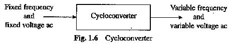
5.Cycloconverter
Cycloconverter (Fig. 1.6) converts fixed voltage and frequency ac to variable voltage and variable frequency ac. They are built using thyristors and are controlled by firing signals derived from a low power control unit. Output frequency is restricted to 40% of supply frequency in order to keep harmonics in the output voltage and source current within acceptable limits.
(b) Variable Impedances
Variable resistors are commonly used for the control of low cost dc and ac drives and are also needed for dynamic braking of drives. Variable resistors may have two (full and zero) or more steps– and can be controlled manually or automatically with the help of contactors. Stepless variation of resistance can be obtained using a semiconductor switch in parallel with a fixed resistance; variation of duty ratio of the switch gives a stepless variation in effective value of the resistance. In high power applications liquid rheostates, known as slip regulators, are employed to get stepless variation of resistance.
Inductors, usually in two steps (full and zero), are employed for limiting the starting current of ac motors. Old drives may also employ saturable reactors for the control of induction motors. In saturable reactors, reactance is controlled steplessly by controlling dc current of the control winding.
(c) Switching Circuits
Switching operations are required to achieve any one of the following: (i) for changing motor connections to change its quadrant of operation, (ii) for changing motor circuit parameters in discrete steps for automatic starting and braking control, (iii) for operating motors and drives according to a predetermined sequence, (iv) to provide interlocking to prevent maloperation and (v) to disconnect motor when abnormal operating conditions occur.
Switching operations in motor’s power circuit are carried out by high power electromagnetic relays known as contactors. Recently attempts have been made to use thyristor switches. Thyristor switches have disadvantages that they cannot provide perfect isolation between the source and motor circuit. Consequently, contactors continue to be widely used. Switching operation based on load’s particular position is implemented using limit switches.
In the past sequencing and interlocking operations used to be implemented using low power electromagnetic relays. Solid state relays have replaced them almost in all applications. For the implementation of complicated sequencing and interlocking operations, programmable logic controllers (PLCs) are employed.
Sources
In India 1-phase and 3-phase 50 Hz ac supplies are readily available in most locations. Very low power drives are generally fed from 1-phase source. Rest of the drives are powered from 3-phase source; except in the case of traction drives where even at very high power levels, 1-phase supply is used because of economy. Most drives are powered from ac source either directly or through a converter link. When fed directly from 50 Hz ac supply, maximum speeds of induction and synchronous motors are limited to 3000 rpm. For higher speeds, conversion to higher frequency supply becomes mandatory. Low and medium power motors (tens of kilowatts) are generally fed from 400 V supply; for high ratings, motors may be rated at 3.3 kV, 6.6 kV, 11 kV and higher.
In case of aircraft and space applications, 400 Hz ac supply is generally used to achieve high power to weight ratio for motors.
In main line traction a high voltage supply is preferred because of economy. In India 25 kV, 50 Hz supply is employed. In underground traction major expenditure is cost of the tunnel which should be minimised by keeping its cross-section just enough for the train. Consequently, clearance between live conductor and the earth has also to be minimum. In view of this, underground traction systems employ a low voltage (500 to 750 V) dc supply. In Western India (Bombay to Igatpuri) 1500 V dc is used for main line and the suburban traction which is uneconomical, and therefore, future installations will not use it.
Some drives are powered from a battery, e.g. fork lift trucks and milk vans. Depending on size, battery voltage may have typical values of 6 y, 12 V, 24 V, 48 V and 110 V dc. Another example of drives fed from a low voltage dc supply is solar powered drives used in space and water pumping applications. These drives, though presently very expensive have a great future for rural water pumping and low power transport applications.
Although choice of a motor does depend on the type of supply but there are many other factors which are even more important. Therefore, a dc motor may be preferred over ac even when the ac supply is available and ac motors may be preferred over dc even when the supply is dc.
Control Unit
Controls for a power modulator are provided in the control unit. Nature of the control unit for a particular drive depends on the power modulator that is used. Because of their large number, only two cases are discussed here.
When semiconductor converters are used, the control unit will consists of firing circuits, which employ linear and digital integrated circuits and transistors, and a microprocessor when sophisticated control is required. When control of switching circuits is required for any of the purpose described in Sec. 1.3.2(c), function of control unit will be to provide sequencing and interlocking. As already stated, solid state relays are used and when control is complex programmable logic controllers (PLCs) can be used.