Resonant Transformers:
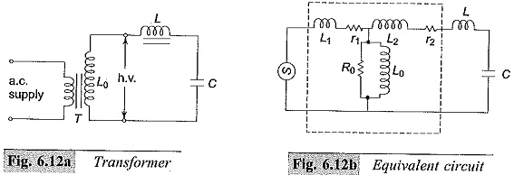
The equivalent circuit of a high voltage testing Resonant Transformers consists of the leakage reactance of the windings, the winding resistances, the magnetizing reactance, and the shunt capacitance across the output terminal due to the bushing of the high voltage terminal and also that of the test object. This is shown in Fig. 6.12a with its equivalent circuit in Fig. 6.12b. It may be seen that it is possible to have series resonance at power frequency ω, if (L1 + L2) = 1/ωC. With this condition, the current in the test object is very large and is limited only by the resistance of the circuit. The waveform of the voltage across the test object will be purely sinusoidal. The magnitude of the voltage across the capacitance C of the test object will be
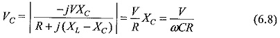
where R is the total series resistance of the circuit.
The factor XC/R = 1/ωCR is the Q factor of the circuit and gives the magnitude of the voltage multiplication across the test object under resonance conditions. Therefore, the input voltage required for excitation is reduced by a. factor 1/Q, and the output kVA required is also reduced by a factor 1/Q. The secondary power factor of the circuit is unity.
This principle is utilized in testing at very high voltages and on occasions requiring large current outputs such as cable testing, dielectric loss measurements, partial discharge measurements, etc. A transformer with 50 to 100 kV voltage rating and a relatively large current rating is connected together with an additional choke, if necessary.
The test condition is set such that ω(Le + L) = 1/ωC where Le is the total equivalent leakage inductance of the transformer including its regulating transformer.
The chief advantages of this principle are:
- it gives an output of pure sine wave,
- power requirements are less (5 to 10% of total kVA required),
- no high-power arcing and heavy current surges occur if the test object fails, as Resonant Transformers ceases at the failure of the test object,
- cascading is also possible for very high voltages,
- simple and compact test arrangement, and
- no repeated flashovers occur in case of partial failures of the test object and insulation recovery. It can be shown that the supply source takes Q number of cycles at least to charge the test specimen to the full voltage.
The disadvantages are the requirements of additional variable chokes capable of withstanding the full test voltage and the full current rating.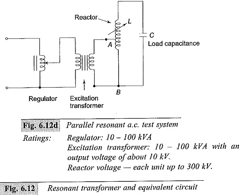
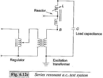
A simplified diagram of the series resonance test system is given in Fig. 6.12c and that of the parallel resonant test system in 6.12d. A voltage regulator of either the auto-transformer type or the induction regulator type is connected to the supply mains and the secondary winding of the exiciter transformer is connected across the H.V. reactor, L, and the capacitive load C. The inductance of the reactor L is varied by varying its air gap and operating range is set in the ratio 10 : 1. Capacitance C comprises of the capacitance of the test object, capacitance of the measuring voltage divider, capacitance of the high voltage bushing etc.
The Q-factor obtained in these circuits will be typically of the order of 50. In the parallel resonant mode the high voltage reactor is connected as an auto-transformer and the circuit is connected as a parallel resonant circuit. The advantage of the parallel resonant circuit is that more stable output voltage can be obtained along with a high rate of rise of test voltage, independent of the degree of tuning and the Q-factor. Single unit Resonant Transformers test systems are built for output voltages up to 500 kV, while cascaded units for outputs up to 3000 kV, 50/60 Hz are available.